10-meter 6-element Yagi monoband – my latest love 🙂
Intro
There is no such thing as “the best antenna.” As with anything, there is a purpose, there are constraints and KPIs. Thus, in the realm of constraints, there is “the best antenna” but not “just the best antenna” 😉
By the way, “I know at least one hundred top ten dive sites” 🙂
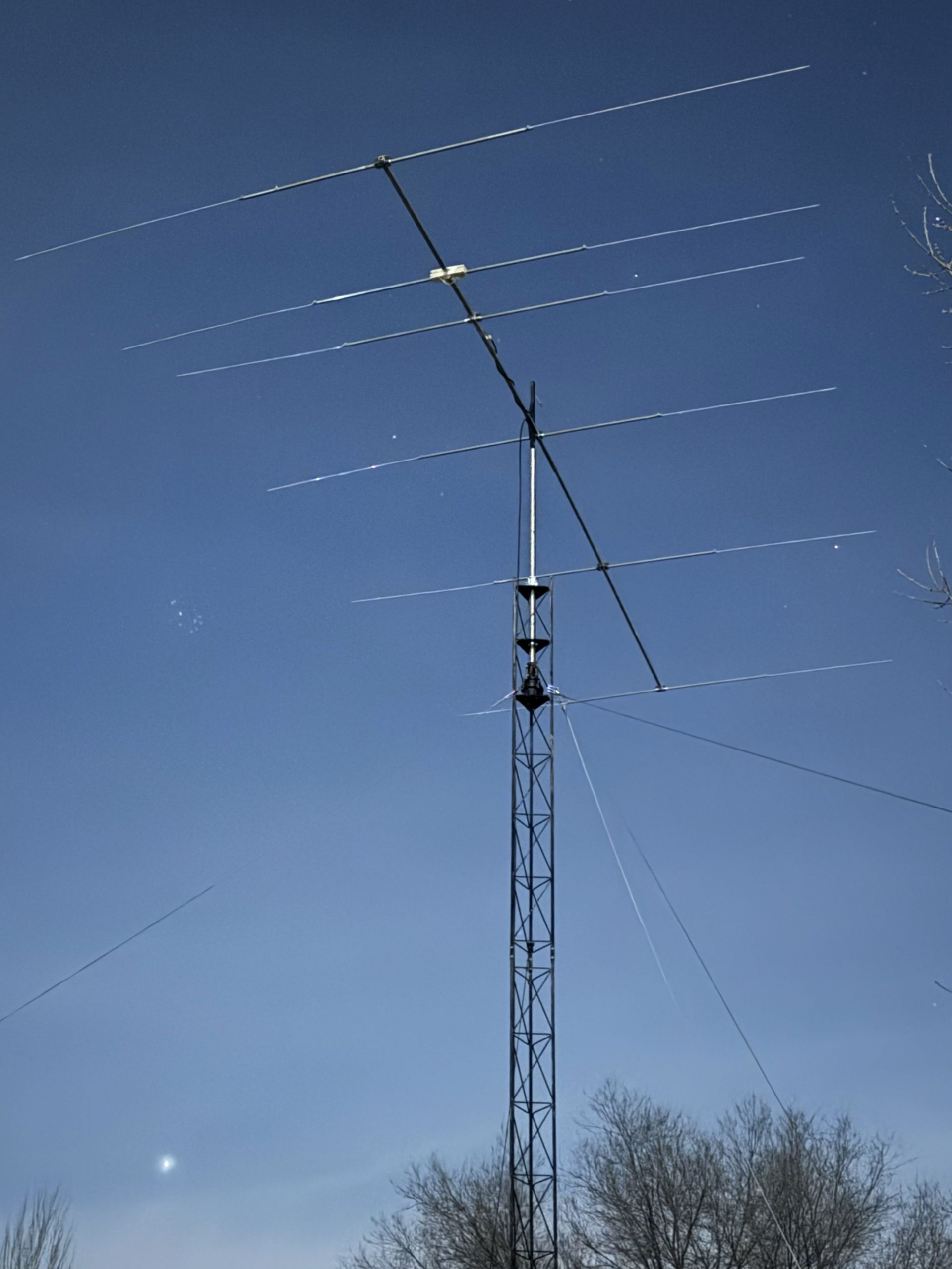
6-element monoband - my latest love
Nevertheless, there are “the best antennas” depending on your selection criteria:
I love raised 1/4-wave verticals with resonating radials. The are the best because:
- Extremely simple – great for field operations, particularly, when external noise is low
- Robust against the wind even with the simplest installations
- Non-obtrusive – you can agree with your neighbors without going to court or bloody fight 🙂
- Perform rather well for DXing despite being omni-directional
- It is omni – I love using it along with with directional antennas to see what is going on around
- You can easily put several tubes along and make the antenna multi-band
Moxon is the best because:
- With such a simple structure you can get 1.5-2x S-level gain against the raised verticals
- Moxon, achieves the highest “value for money” – the highest gain and benefits for DXing for the level of efforts, costs, size, and complexity
- It has a much lower noise than 1/4-wave because of the antenna diagram
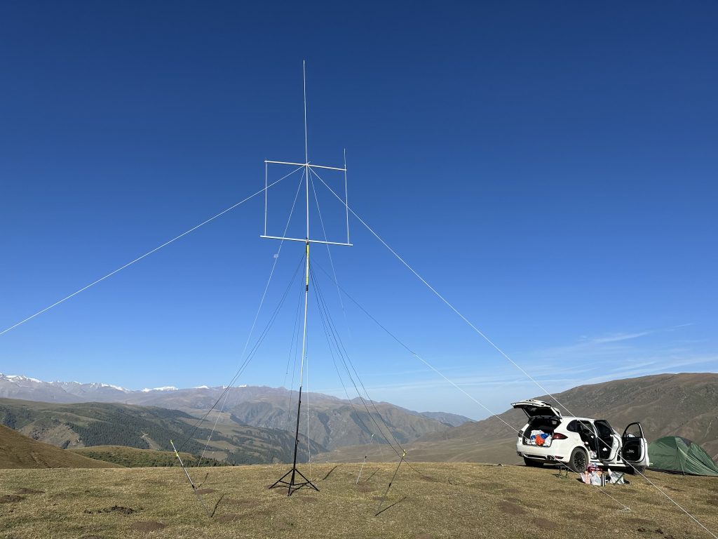
- Light and compact – super-important for traveling – you simply save money on baggage
- Beautiful for field of operations in conjunction with fiberglass or carbon telescoping masts having 10-20-meter heights (I am referring only to 10-15-meter bands, because it is nearly a peak of the sun 11-eleven year cycle, and the bands are true fun) – easy and fast to deploy (in field of operations). You can sit in your car or even under the antenna and rotate the antenna manually
- Tunes to a 50-Ohm cable with low SWR directly (a balancing ferrite ring is always recommended)
Yagi monoband is the best:
- The highest achievable gain with still reasonable investments – typically, you don’t want your work or family life suffer too much simply because you want to build a 8×2 array for the 20-meter band… However, I don’t see any reasons to suppress such a wonderful desire too much – to build the 8×2 array 🙂
- Tunes to low SWR well with a wideband design with special director close to the driver (see the design below)
- Tunes to low SWR well even with the tubes are not exactly the same diameters (but be reasonable)
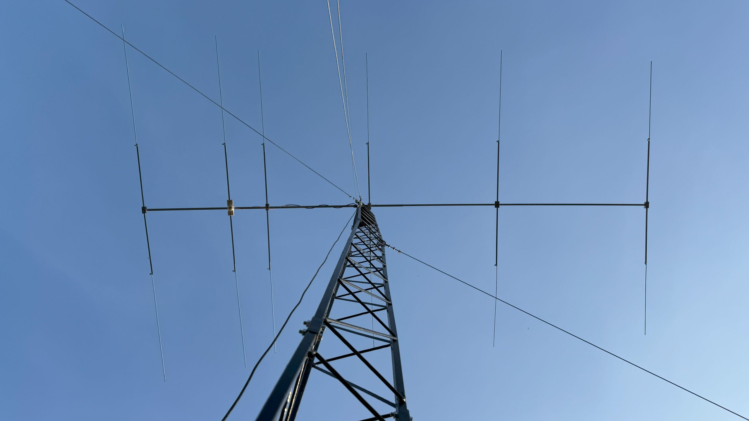
I loved that Moxon single-handedly beat my previous favorite – the 1/4-wave raised vertical. I very much wanted to repeat the same feat with the Moxon-Yagi pair. So, despite the 6-element Yagi presumably (and obviously) better on paper with it’s high-gain, low-to-the-horizon beam, etc. than Moxon, the number one criteria for the success was to beat Moxon that was already very good.
To beat is a complex term. To beat in what?… :
- Gain?
- Noise?
- Signal/noise?
- DXing over long-distance?
- Easiness to use in practice – no need to rotate it all the time
There are many criteria and “to beat” can be not as obvious.
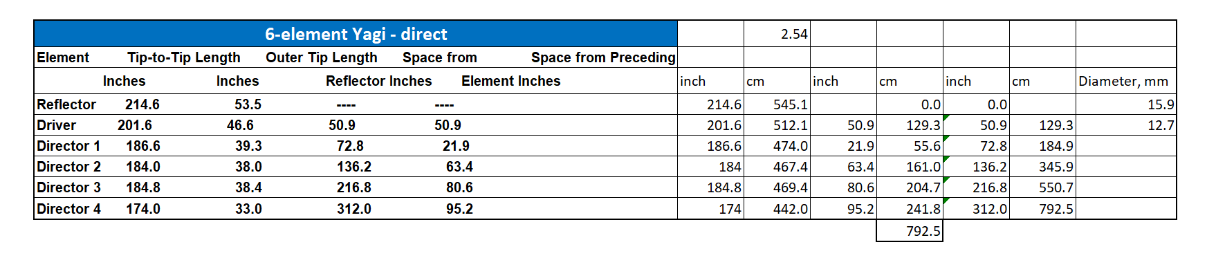
Since this was my first ever Yagi, I simply used a design that found in the internet and which after it proved to be good, I clearly can recommend:
I checked quite a few other designs but the more I studied them the more I liked the approach described by W4RNL. The matching game didn’t make me enthusiastic:
I didn’t need the wideband of the W4RNL design. But I truly liked the beauty of the “matching solution”. If it brings the widebandness along the way, it makes it even more beautiful.
I hesitated a bit, since it was my first Yagi, and thought that, perhaps, I needed to start with something much simpler: No. 43: A Small 10-Meter Very-Wide-Band Yagi.
However, I wasn’t sure the smaller-gain Yagi will decisively beat the Moxon and I didn’t want to risk and close the journey towards the high-gain Yagis simply because the first experience with Yagi wouldn’t be as spectacular as it could be because I choose the easier path and the win of Yagi over Moxon wasn’t that great.
The second point for consideration was the matching. Moxon is so great that it doesn’t need any external matching circuit. This spoils. I really wanted the same with “cooler and stronger Yagi” because otherwise would be a step back in progress, a downgrade – to have it in Moxon and even in the raised 1/4-wave verticals and then suddenly lose it in Yagi that was supposed to be cooler than the previous two.
However, I needed to play safe and bought a hairpin matching as well, which I didn’t eventually use since I chose the design that provided the 50-Ohm match right away.
When you build antennas, especially, when you take somebody’s else design, it is important to keep dimensions as close as possible including the diameters of the tubes and the boom.
However, it is easier to say than to do because some particular easy-to-find tubes from the US hardware stores may not necessarily available in your country and wise versa. At the same time, there is no point to use the design solutions blindly. Often, it is not as bad if you keep the dimensions close enough and understand that, for example, larger diameter will lead to smaller length, you can be OK with the components you can get from your local hardware store.
See below the dimensions that I used in my antennas – copy-paste from the original design.
I was trying to purchase aluminum tubes of needed diameter according to the design but after spending 2-3 days in fruitless talks, I realized that local sellers are interested to sell in tons, they over-promise and under-deliver, and I still need wait 5-7 days at minimum. It was too much for me.
Thus, I built the antenna from what was available in the local Leroy Merlin (a hardware retail chain). Previously, they used to have a larger variety of aluminum tubes but not anymore. Thus, my choice was even more limited than it could have been. Nevertheless, everything worked out very well.
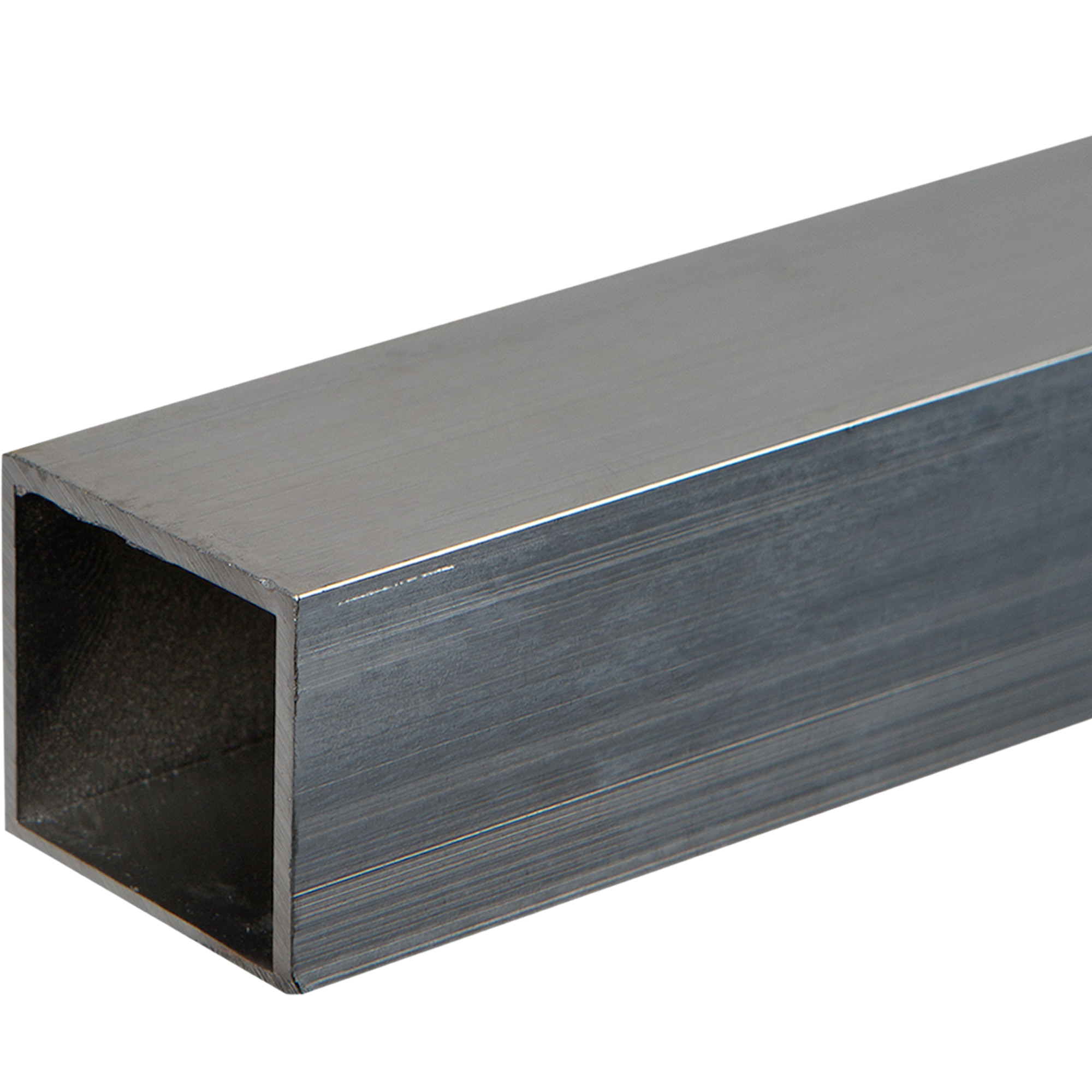
Boom
- Built of 4 pcs of 2-meter square-shaped aluminum: 30x30x1.5mm + 30x30x1.5mm + 25x25x1.5mm + 25x25x.15mm. I was inspired by this company. Though, I wasn’t sure that the 50x50mm or 60x60mm booms they use are really required taking into account the hugely increased weight of the antenna
- The total length of the Yagi is just under 8 meters – see the table above
- The 30x30mm tube is closer to the reflector – where more elements are packed more densely
- The 25x25mm tube is on the opposite side where only a couple directors are
Thus starting from the farther tip of the boom to the reflector:
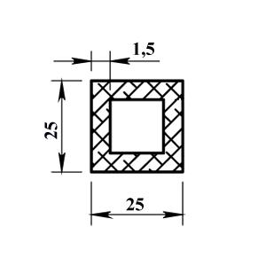
- Square Tube 1: 25x25x1.5×2000 mm
- Then, there is a 20x20x1.5×300 mm square Junction 1-2 inside the Tube 1 to hold together with the Tube 2
- Square Tube 2: 25x25x1.5×2000 mm – identical to the Tube 1. It enters with another end into Tube 3 for 8 cm
- Square Tube 3: 30x30x1.5×2000 mm
- Between the Tube 3 and Tube 4, there is a square Junction 3-4 25x25x1.5×300 – similar to Junction 1-2 but 25×25 mm of size
- Square Tube 4: 30x30x1.5×2000 mm
Elements
- The tips – regular 10x2000x1 mm aluminum tubes
- The center part – 18x13x1.5×2000 mm H-profiles – see the picture below
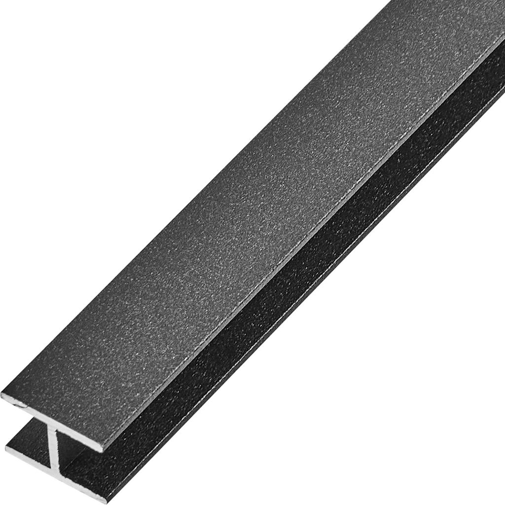
The beauty of the solution is that the H-profile is rigid on the one hand and good for the central part of the element and it has a larger diameter, thus making it easier to achieve higher bandwidth. On the other hand and that is the key, it can tightly hold the 10mm tube inside. The 10-mm tube sits inside the H-shape part very tightly but comfortably since aluminum is a soft metal. Thus, you can make any required length of the antenna element and change it very easy – like a length of trombone. You don’t drill anything and don’t weaken the design. You can play with your antenna design as much as you wish.
I find this method of joining elements fore more appealing than making the holes because making the holes immediately creates two serious problems:
- Making the joint weaker
- Removing the flexibility to tune the antenna if needed
The whole joy of playing with antenna is that you can tune it easily. If you drill and screw the elements, you cannot tune the antenna really.
Below is the picture that W4RNL suggests but I cannot recommend it:
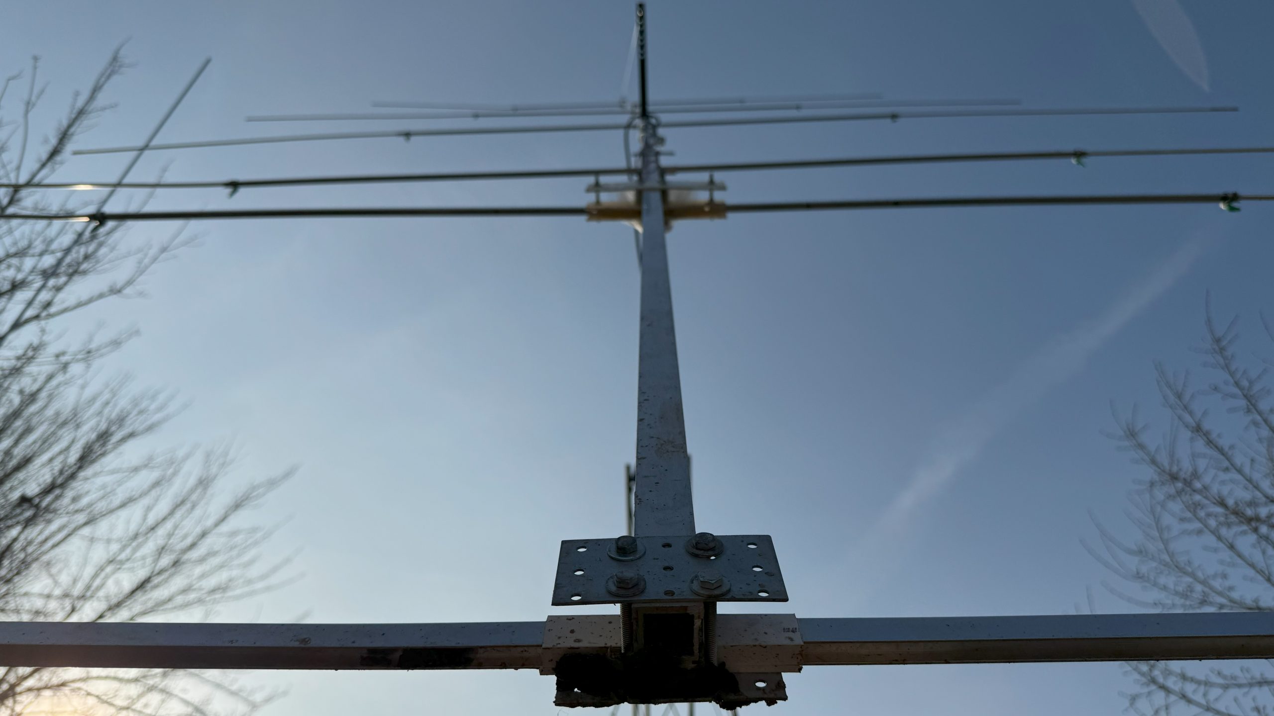
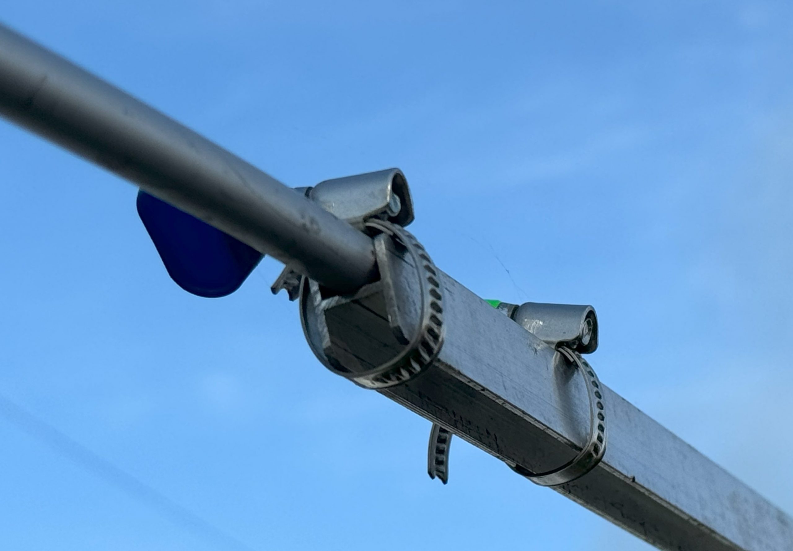
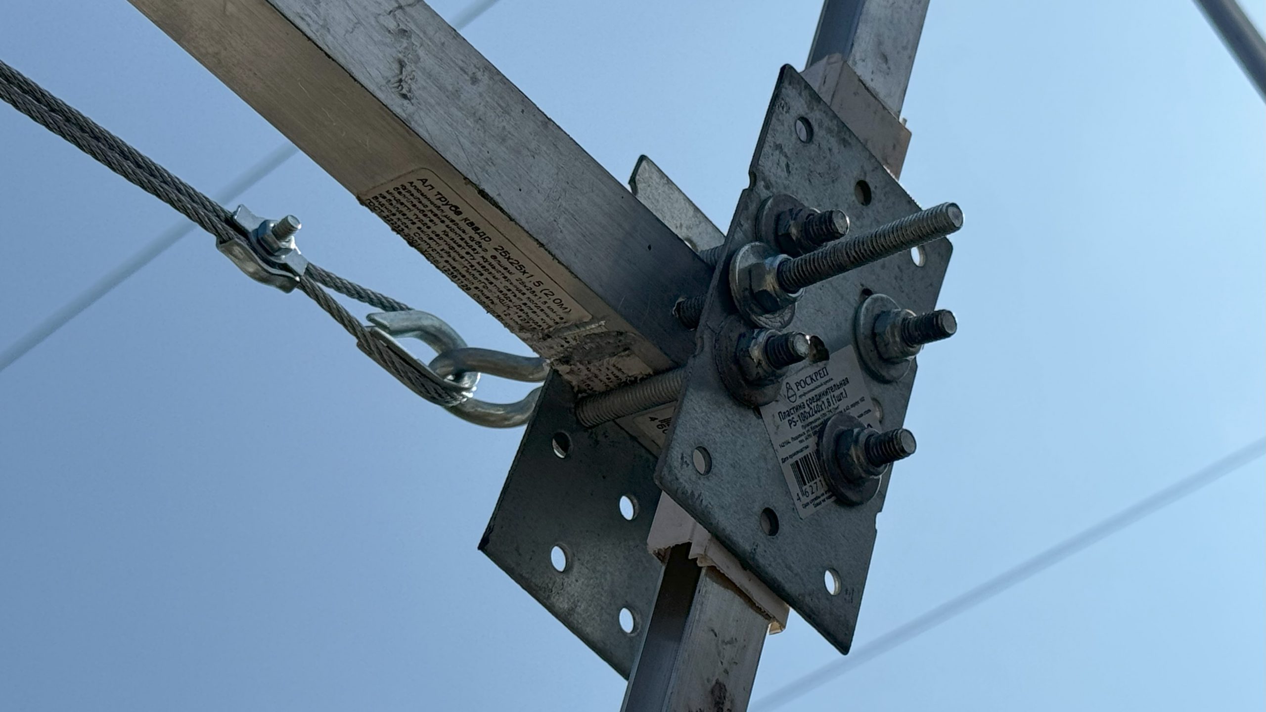
Attaching elements to the boom
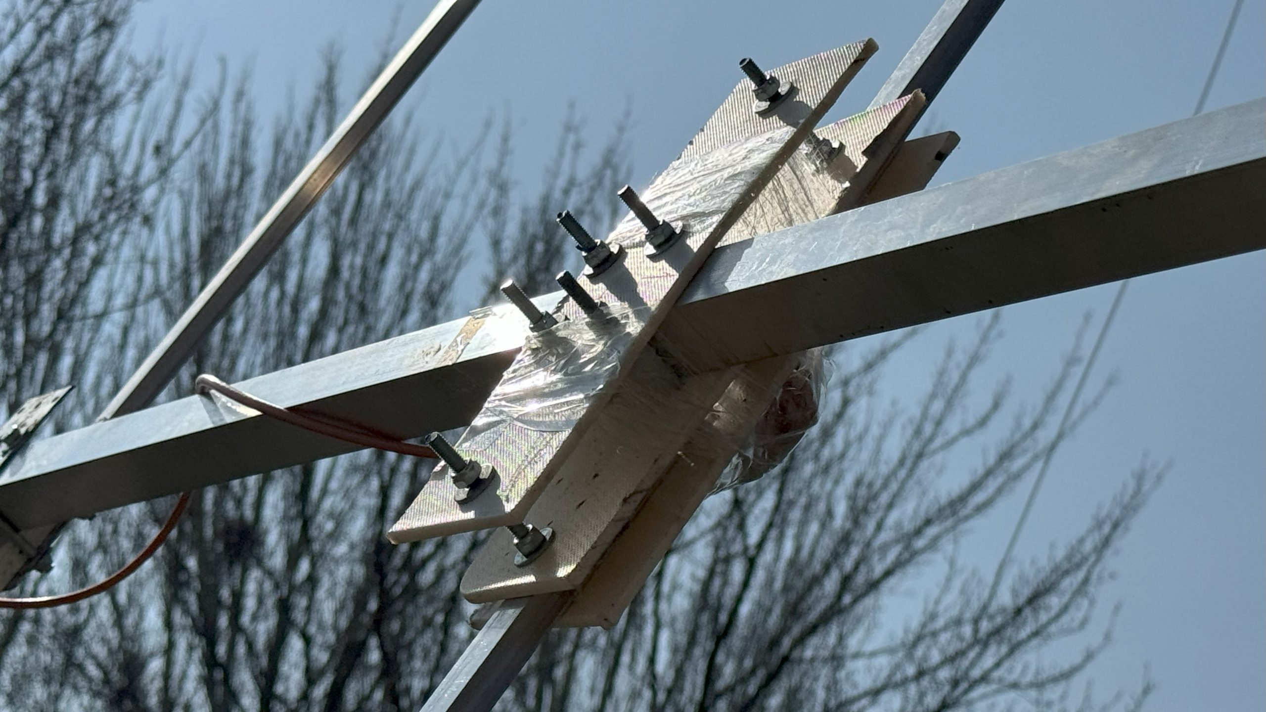
The front director is similar to other directors and the reflector. See the photo below.
It is using:
- Two steel plates to hold the director against the boom
- 4 pcs of 6×60 mm bolts stitching everything together. They prevent the element turning against the boom
- The director is isolated from the boom by the plastic that was also purchased in Leroy Merlin – it is used to cover the cables (Ethernet, electricity) inside the rooms. Coincidentally, the external dimensions of the H-shaped aluminum part and the inner part of the plastic matches very well
Middle director:
Reflector:
Notice that all elements are isolated from the boom. I don’t know what practical difference it has as compared with the electrically connected booms. But I wanted to play safe and since the original design used the isolated from the boom elements, I used a similar design as well.
However, as with practical details, I had to adopt what was available. I could have 3D-printed holders, etc. But I didn’t feel this complication was necessary. The basic plastic rectangular-shaped white tube worked well for the design as an insulator.
Attaching the driver to the boom
Driver is the most complex element. Well, it is not complex at all, simply, the other elements are even more primitive.
The driver is split into two parts. Thus, a different solution is implemented to keep the elements solidly together.
Below the white plastic isolating sheets (purchased in the same show – a plastic to cut vegetables), you can see a balancing transformer wrapped into a tape.
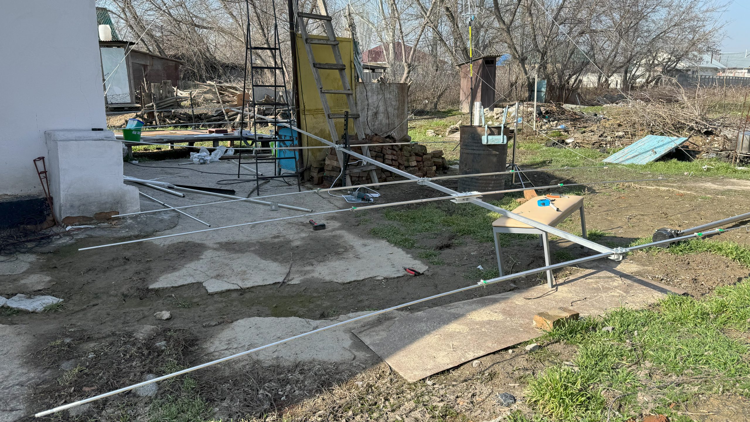
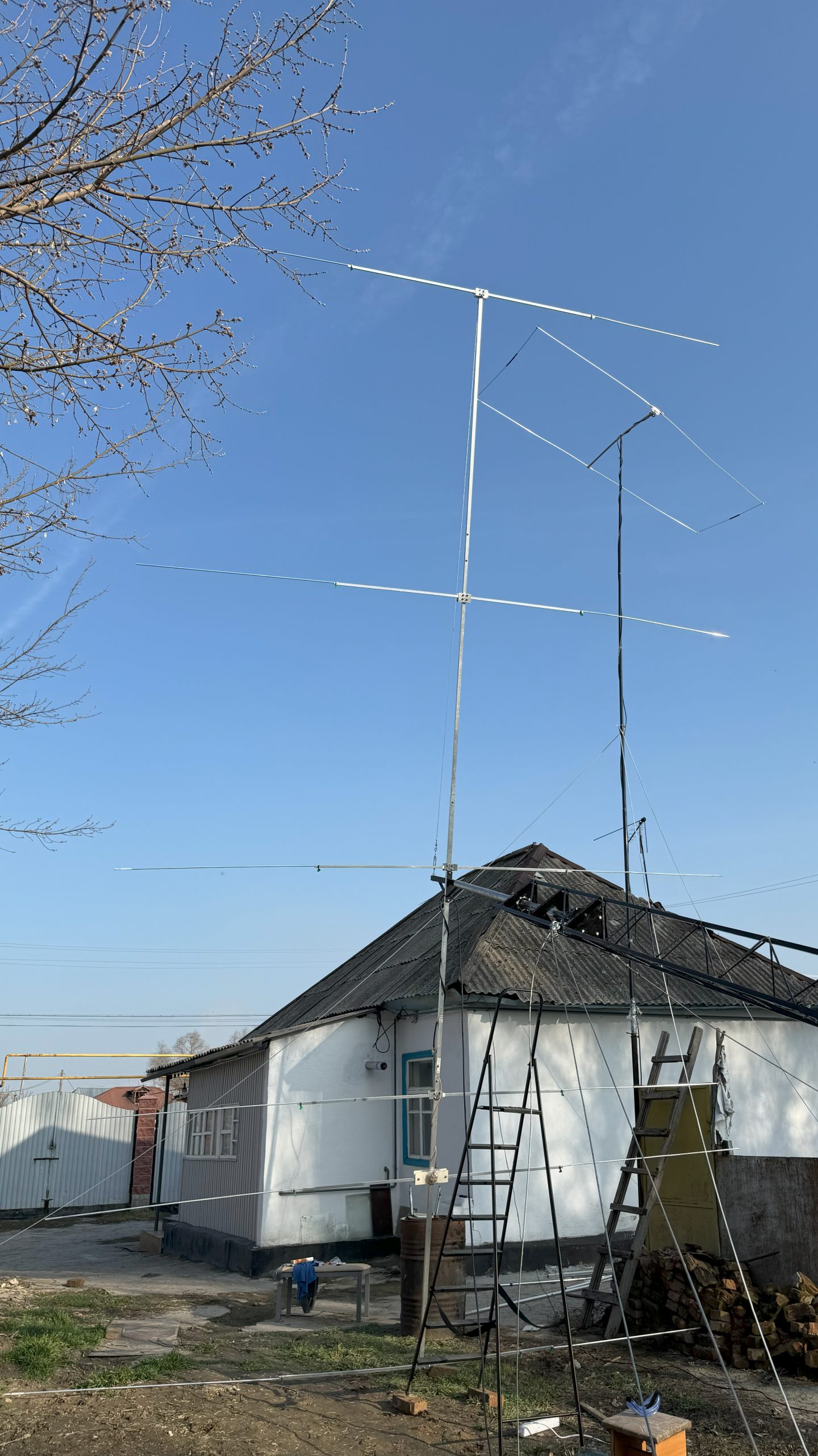
Attaching the Yagi to the mast's tube
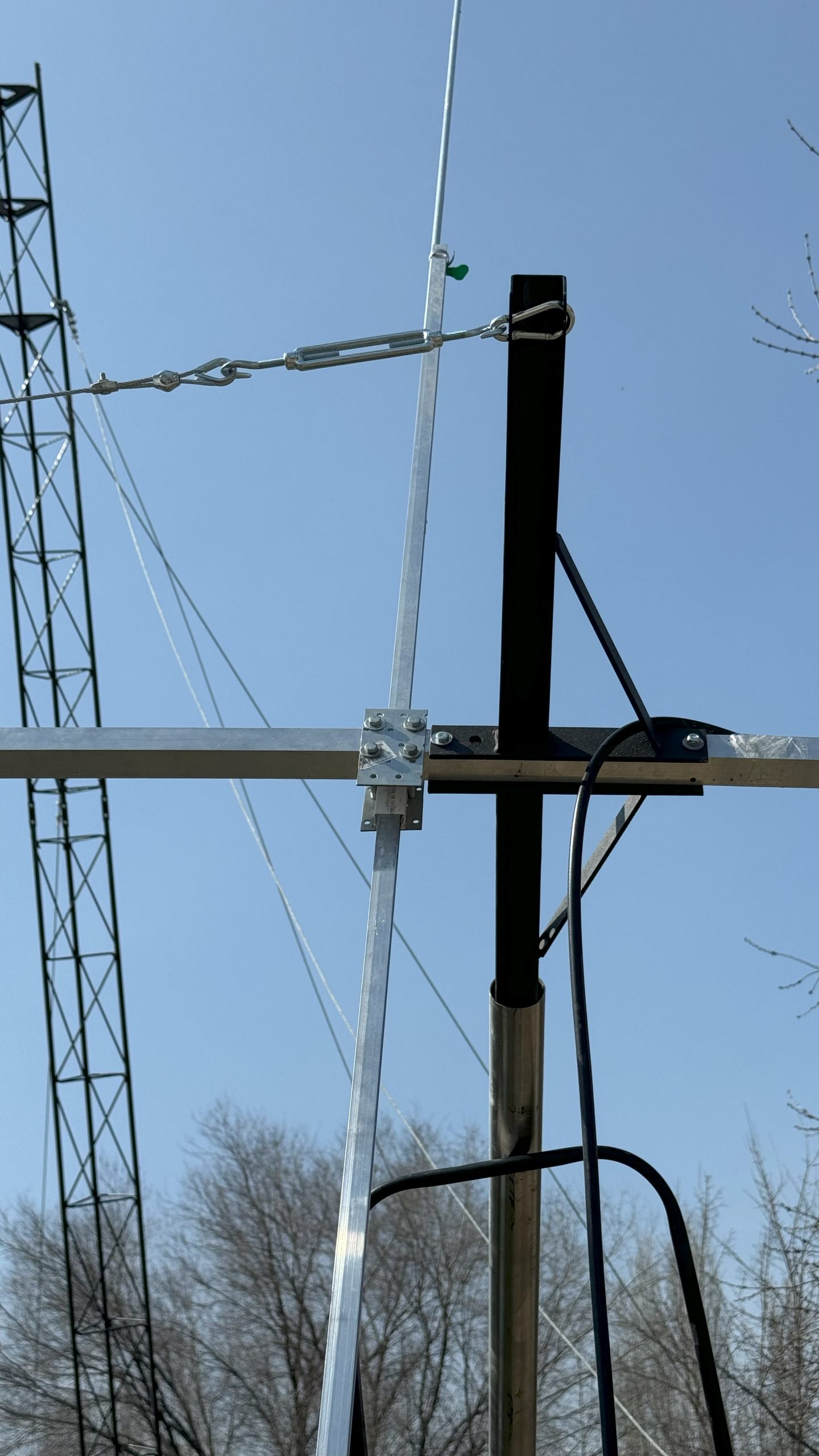
I planned to put a 6-meter 50-mm stainless 1.5 mm tube inside the rotor, raise the whole thing and to have Yagi on 15 meters. However, my plot of the cottage that I rent is full of unfinished concrete construction debris and other garbage. I simply don’t have space for guying of such a setup or I would have to to move the whole antenna 20 meters further from my shack to a non-fenced area, which I didn’t want to do because of excessive cable losses and the risk for the antenna being vandalized.
Thus, I had to limit myself to just a 2-meter tube on top of the 9-meter mast. The tube is about 1 m inside the mast and 1 m outside.
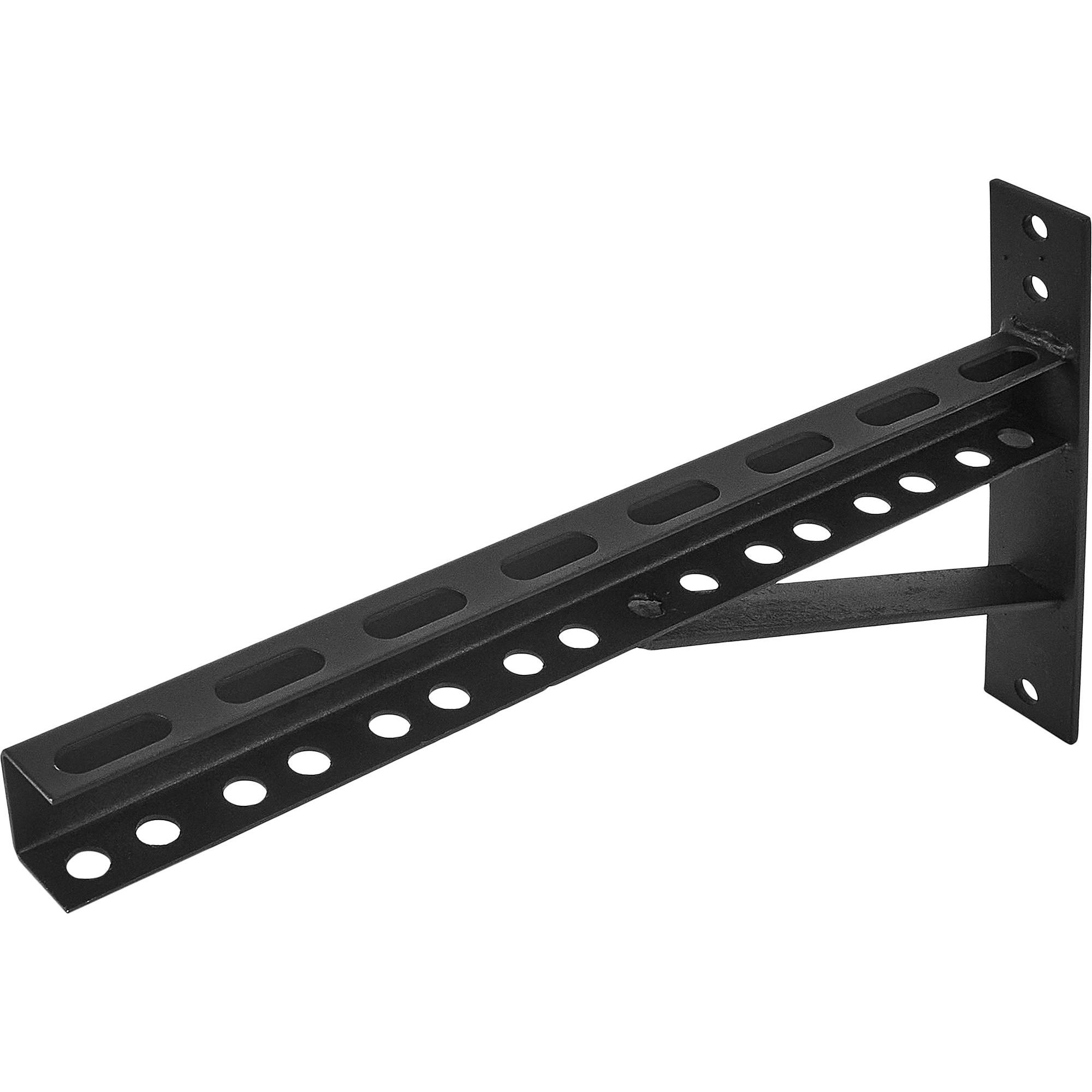
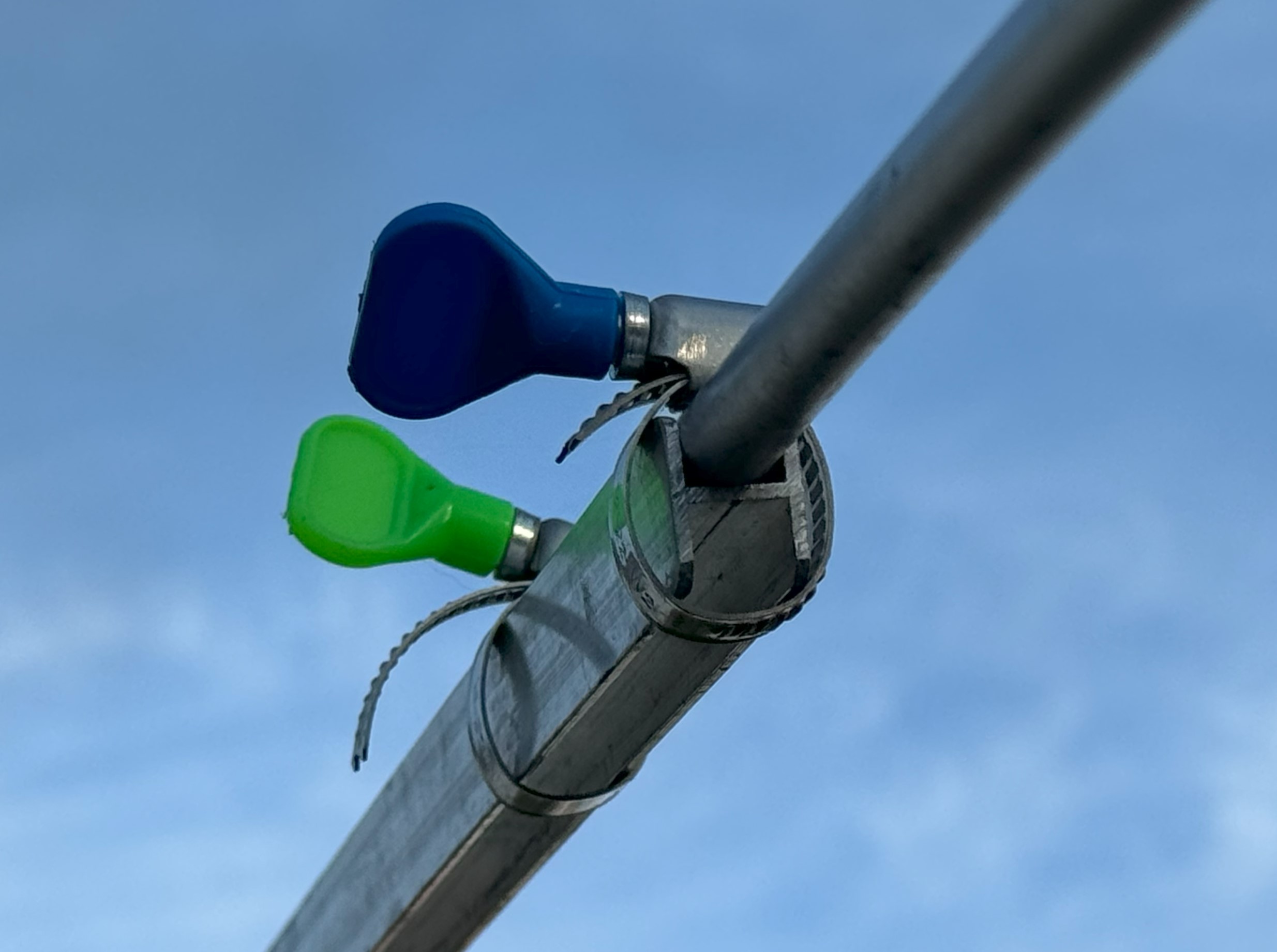
Thus, the antenna got two special T-shaped structures also purchased from Leroy Merlin. Again, it is not because I particularly loved the elements but because they could be quickly purchased and they seemed to the job:
One of these elements is below the boom and is insirted into the 50-mm mast’s tube where it sits tight because of the dimensions because it is additionally secured by a 6×60 mm bolt. And another identical element is above the boom – it is used along with the stiffener of the boom. See the first director.
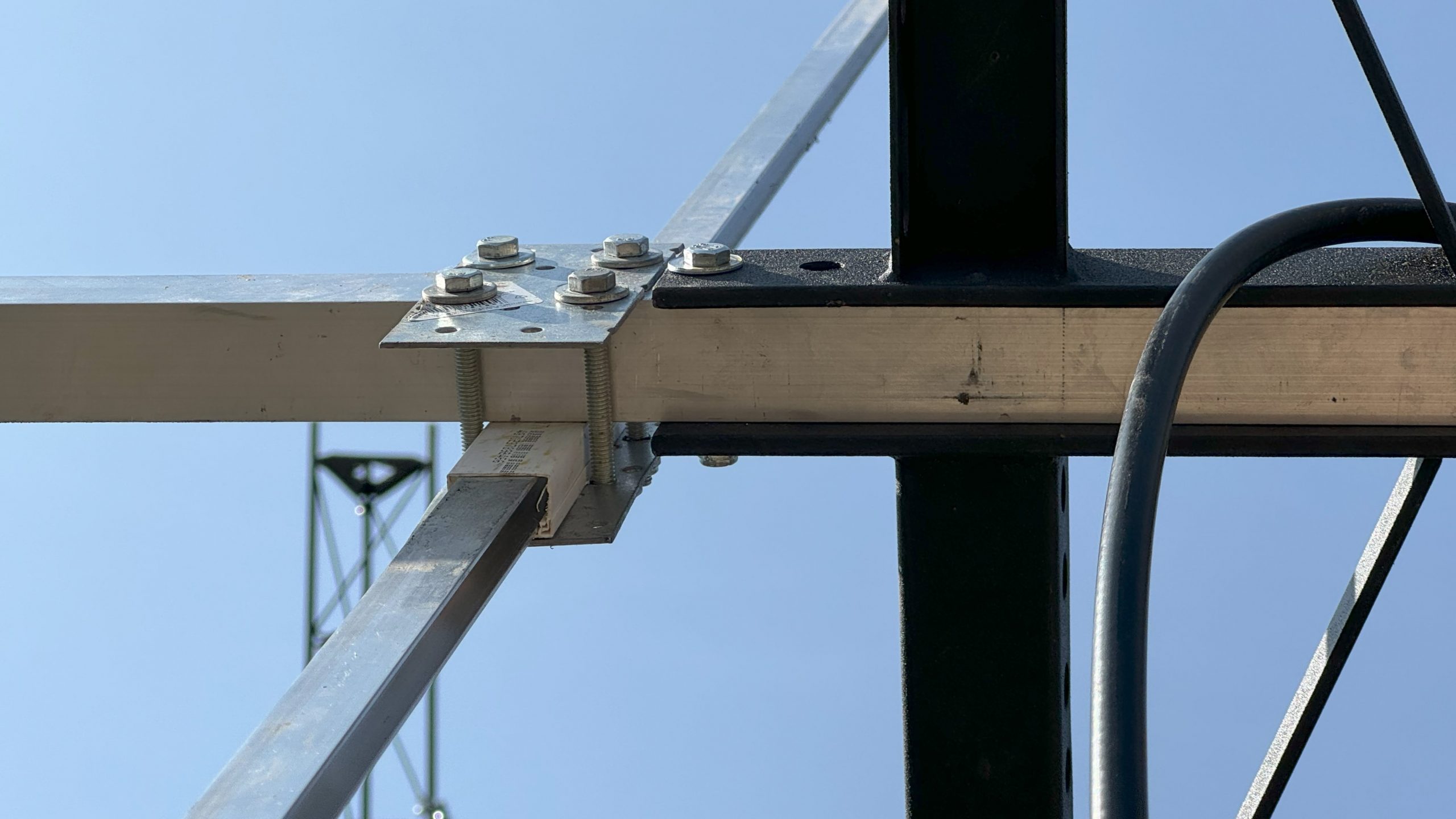
There is a single 6-mm hole in the 50-mm mast tube. A 6x60mm bolt keeps the element and the entire antenna inside the tube.
Having such a structure makes it possible the antenna can be removed from the mast virtually in 1 minute and replaced with another antenna, for example, for testing and comparison or for repair.
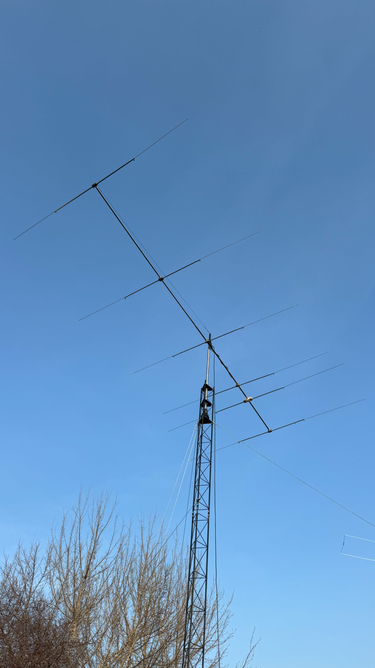
Weight
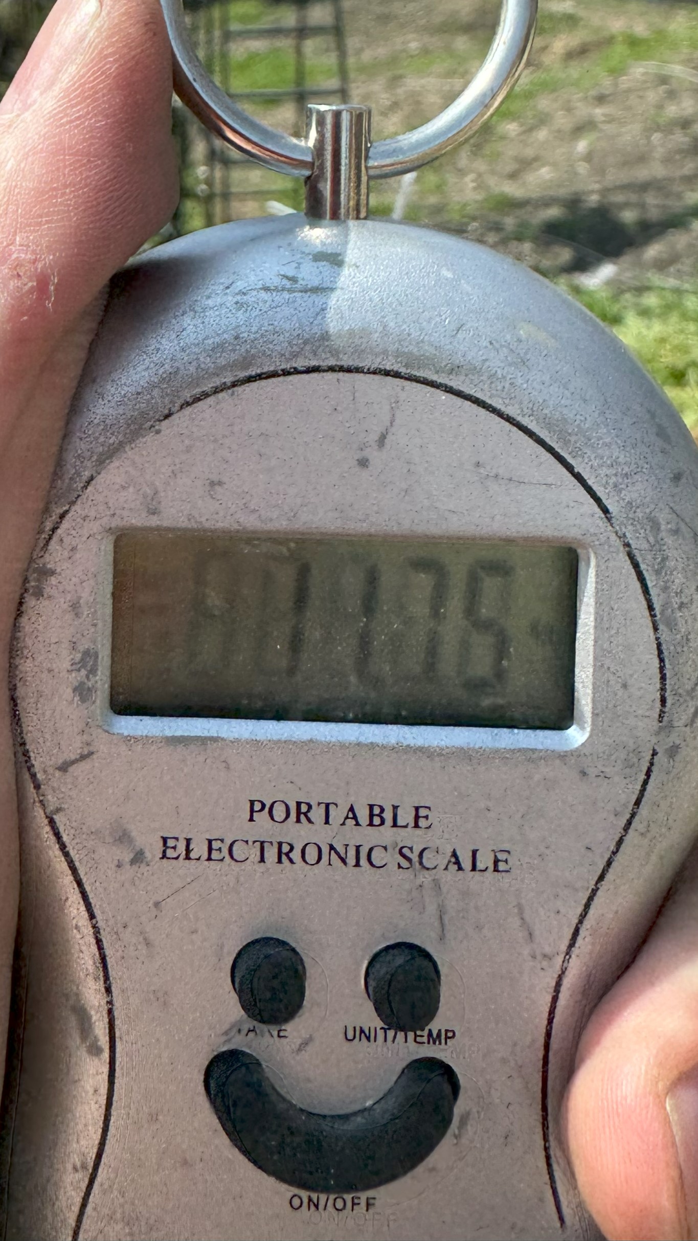
The antenna has a total weight of 12 kg… It looks suspiciously low taking into account that is a 6-element Yagi on a 8-meter boom…
However, I measured several times and still not sure – it shall be more and feels like more – but the meter shows just under 12 kg of weight…
Other comparably sized antennas are significantly heavier – from 22 to 40 kg and that puzzles me:
- Either my meter fools me
- Or I will be penalized later when my antenna collapses because I chose too thin materials
- Or other guys made their antennas too heavy for whatever reasons (wind, coolness, or they colluded with the delivery services and get kick backs from them for over-weighted parcels 🙂
Other commercial designs that i loved and used for references and comparison:
I give advises that I didn’t follow myself 🙂
Unless you have a perfect plot and can install masts and guys according to the blueprint, don’t erect masts alone. Even the small 9-meter mast with a 2-meter 50-mm tube and a 6-element Yagi for 10-meter band is a very big thing.
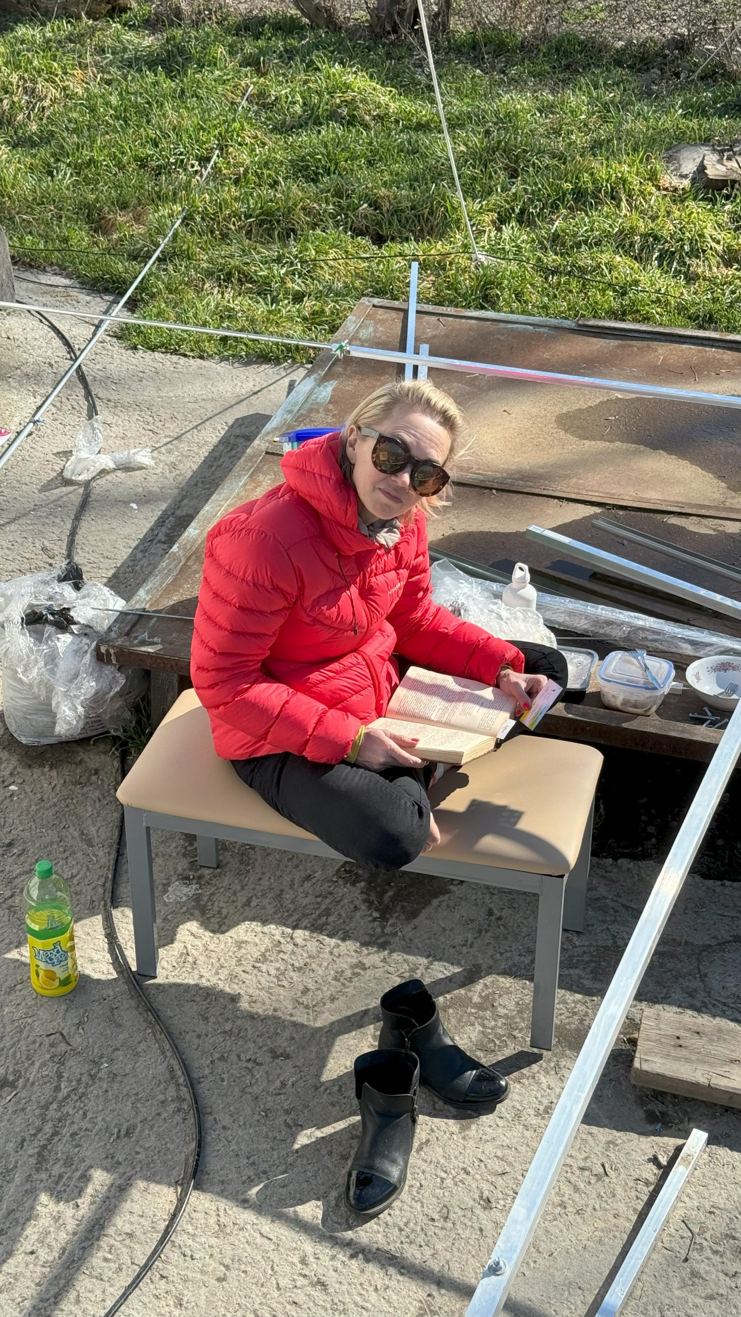
Big means bulky, shaky, and prone to swing to sides (again, unless you have a perfect plot with proper guying). During the hours of construction and installation I so many times needed another pair of hands to prevent something falling and bending – you cannot imagine. Have somebody along. A strong guy would be very helpful. But even your wife can help with something light and simple.
Don’t do it alone 🙂
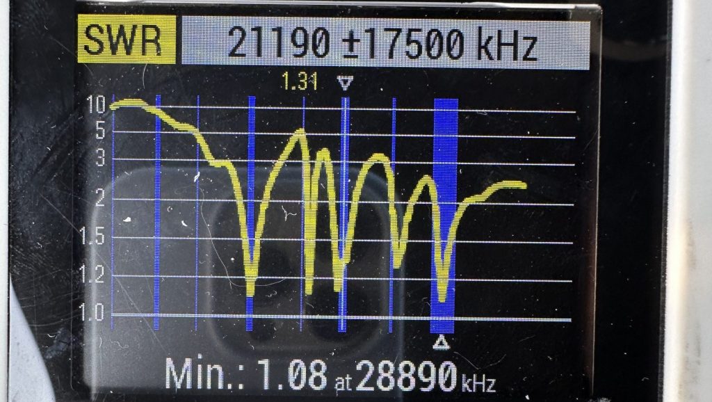
The first most important checkpoint is when you connect the antenna for the first time and measure the SWR. It is a point may send you to joy or dismay. In my case, it was none of those …
The first… and the second and the third measurements showed SWR of 50 or more. There clearly was something wrong.
Then, I spent a couple of hours trying to find the impossible:
- The Ohm meter showed that there is a short-circuit in my radiator. But it was impossible since the gaps were 7-10 mm at least. When you search for impossible, you can easily start fantasizing trying to find an explanation for impossible …
- I had to cut (it was too difficult to bring the soldering iron since the antenna was already 3-4 meters above the ground) the transformer to be sure that the problem isn’t in the transformer. As soon as I did it, it became clear that the problem wasn’t in the radiator. The cable became the prime suspect
- But prior to that, I visually inspected the cables several times and did it closely. They were OK. I also measured the short circuit several times. There was no short circuit. Nevertheless, when assembled together, there was a short circuit again and as result – the SWR of 50. Thus, the impossible was possible …
- Eventually, it turned out to be “a damn Chinese cable/UHF connector assembly”: when no other cables attached, it was OK. But when I connected the main cable to it, it pushed something inside the UHF connector and it created the short circuit. Thus, when measured separately, it showed “I am OK”. But when assembled in the real setup with other connectors, it wasn’t OK anymore
Well, I lost an hour or two just for nothing.
Eventually, I managed to fix the cable and measure the SWR. Surprisingly, it didn’t substantially differ on 3-4 meters height and on 11 meters.
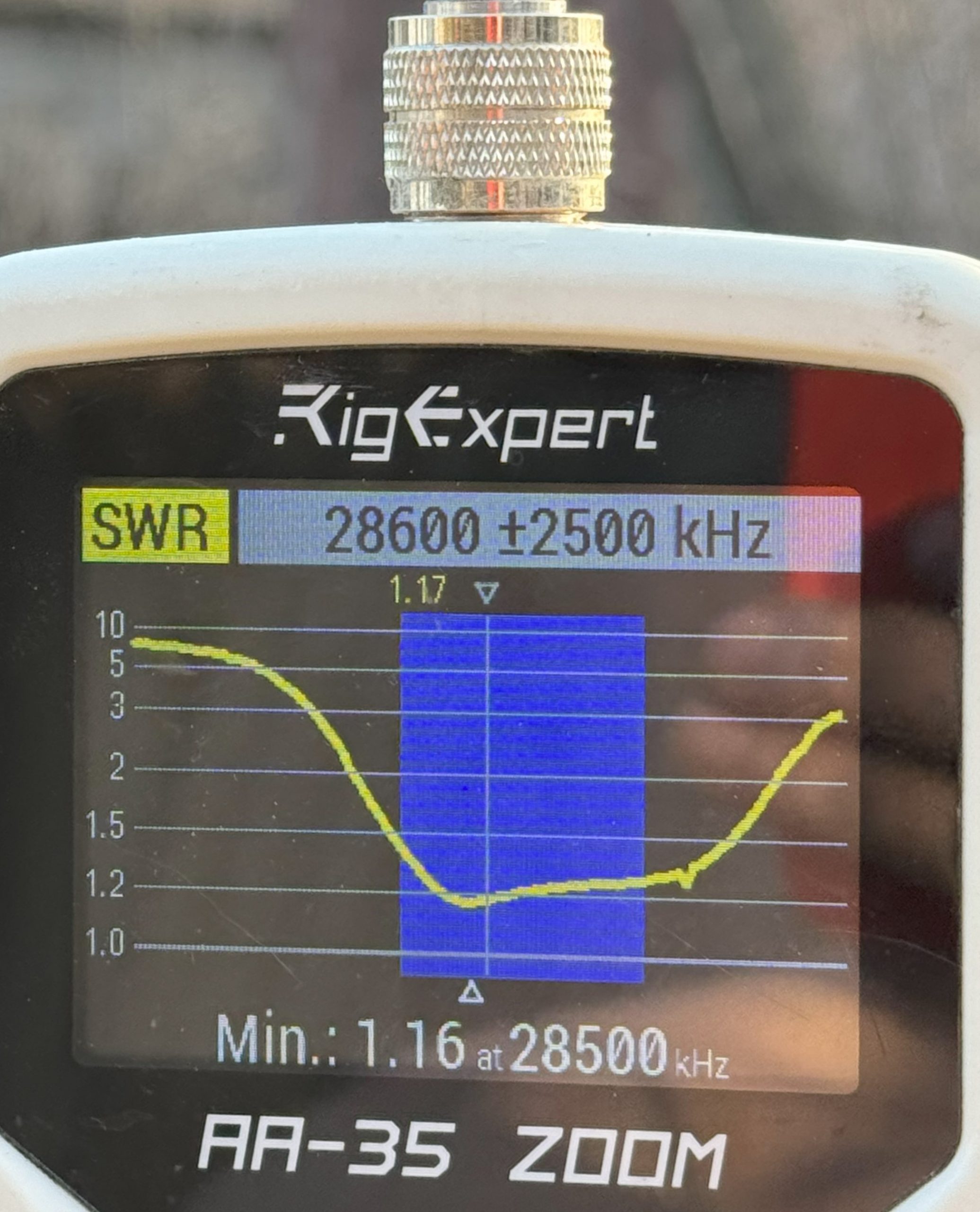
I liked the initial result. Since I have spent so much time and efforts to the moment assembling the antenna, I was eager to listen the air and compare the new Yagi with Moxon as soon as possible. I decided not to play with SWR tuning.
Since other materials (the thicker and lower-loss RG213 cable, the cable to control the rotator, and the power supply converter ~220V to 110V for the rotator) hadn’t had arrived yet, I had to disassemble my other antennas – 15-meter Moxon and even the triple 1/4-wave verticals – to steal the RF cables because I needed just slightly under 40 meters of cable to connect Yagi to the power amplifier.
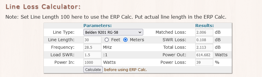
Only the 10-meter cable on the mast of Yagi was a proper RG213 cable – a lower-loss and a higher power cable. The remaining 30 meters were built out of two pieces – 10+20m – of a lossy RG58 cable. Thus, the comparison with Moxon wasn’t fair, since Moxon was connected with a good RG213 all the way along and there was only 20m of it.
Calculations according to https://kv5r.com/ham-radio/coax-loss-calculator/:
For Yagi – 30 m RG58 cable:
And then 10 m of RG213 cable:
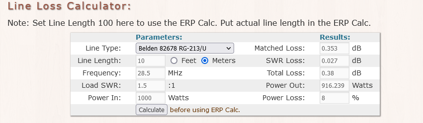
For Moxon – 20 m RG213 cable:
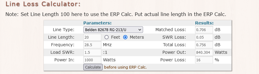
Thus, it was intentionally unfair to Yagi with about 1.7 dB excessive cable loss on reception and transmission for Yagi as compared to Moxon.
The first impression
- About 1-S level gain for Yagi on reception and transmission depending on the direction and correspondent
- Though, with some correspondents, the difference was rather unnoticeable
- About 1-3-S levels lower noise for Yagi, which I didn’t expect
- If you want the highest gain – build Yagi. Feel confident in the air but be ready for substantial efforts
- If you want a high-gain with minimum efforts – build Moxon and truly enjoy it
- I am eagerly looking forward to the opportunity to test the antennas in the air more thoroughly: more QSOs, more distances
- Since the cable for the rotator hasn’t arrived yet, I cannot try different directions. But that will be the first thing after the rotator becomes operational
- Since Yagi has a more rugged diagram with stronger peaks expected towards horizon and also peaks much higher from the horizon than Moxon, it will be interesting to see the results and comparison on the larger distances, middle distances, and shorter distances. There must be areas where Moxon shall be clearly winning. Theory is cool, but it is even more exciting to see it with your real eyes on the map
- Before building a practical thing I was hypothesizing about an idea of playing with a stack of Yagis on 10 and 15 meters or so. Now, I clearly see that I would need a significantly larger space for such endeavor. Thus, it is cancelled for the time being
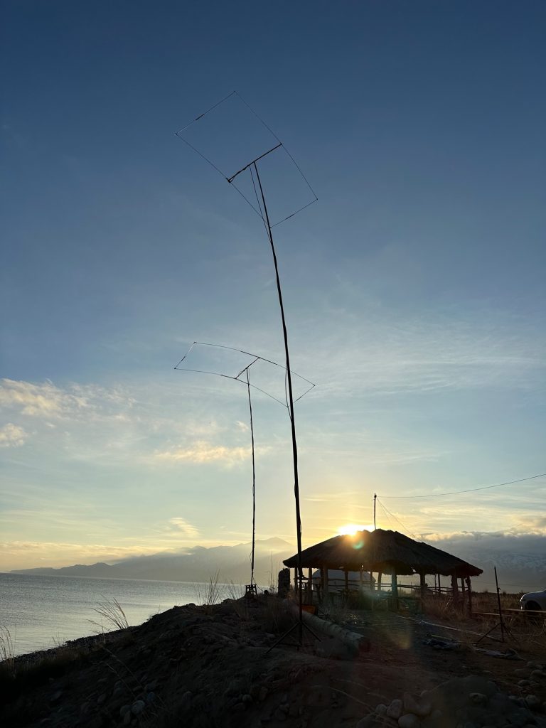
- At the same time, an idea of stacked Moxon to compare with (and beat) the 6-element Yagi looks like an interesting step forward. Moxons are much lighter and smaller
- Perhaps, if I have to put the antenna down and if I manage the process of raising and putting the mast down simpler, I will play with the first director: a) how exactly it affects the matching, b) since I don’t need so much bandwidth, I may play with lowering the SWR. However, the SWR doesn’t mean higher gain. Thus, it is not clear whether it is worth it unless I can find to measure the gain more consistently
Typical Moxon maximum
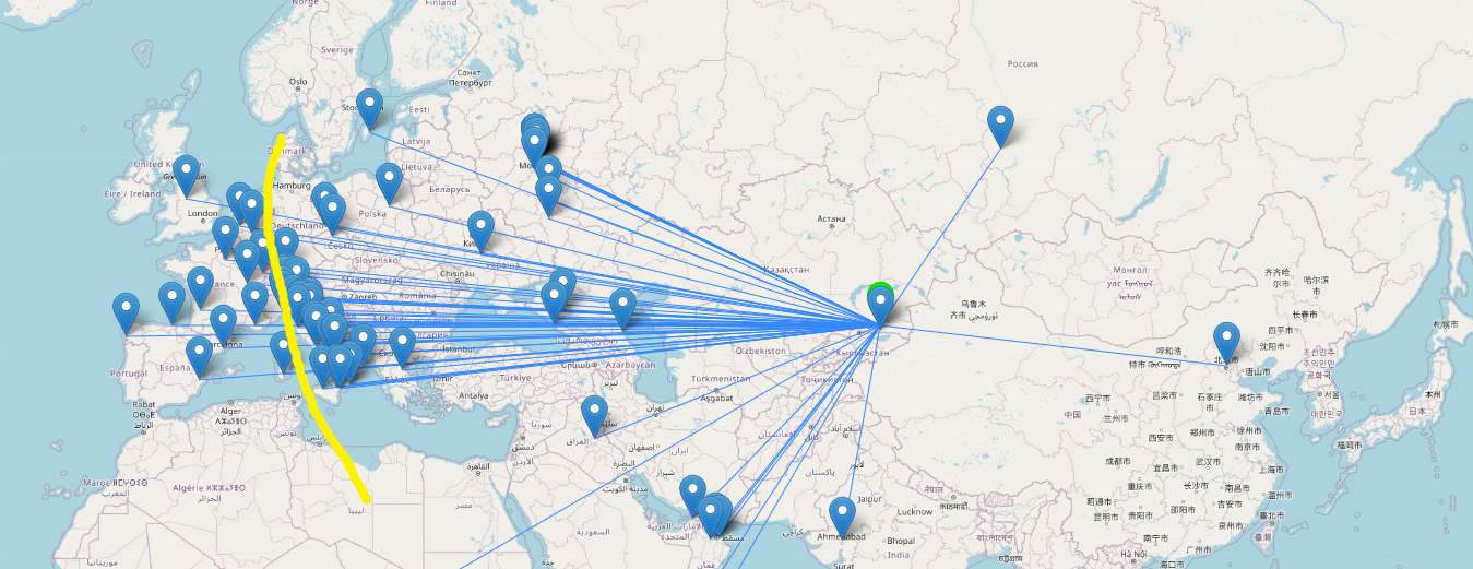
Yagi maximum
It is interesting to see the Yagi’s maximum when you start calling – just be the statistics of replies. However, there are several important notes:
- The statistics is very limited because of limited time
- It was the largest magnetic storm for the last 20 years or so. The shape of ionosphere can be completely different from the shape of ionosphere with the Moxon’s QSO’s several days prior to Yagi’s testing
- The antenna diagram of Yagi is more shredded. Thus, there is one beam high to the horizon and presumably higher than that of Moxon. However, there must be another beam – lower than a single beam of the Moxon. And that beam is for real DXs. However, for real DXs I need farther distances and more statistics points
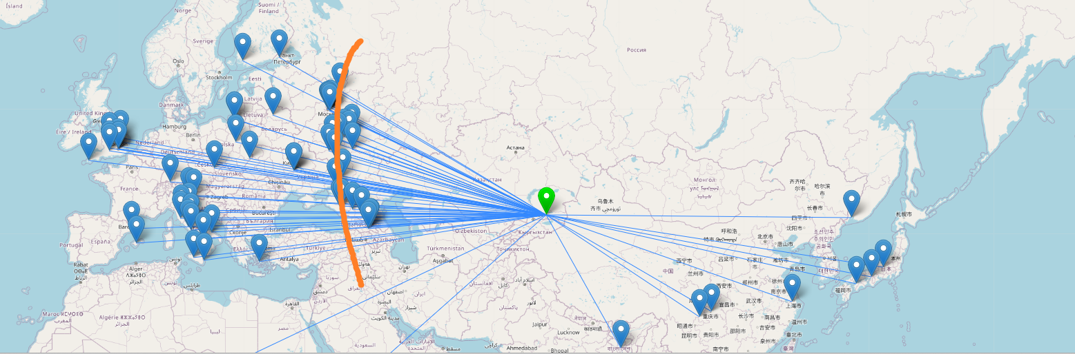
- Yagi showed, at least, 1 x S-level gain over Moxon on the same height and facing the same direction. But far more statistics data from different distances and directions are required to make the statement for substantial. It is just the first impression
- Yagi showed noise less than S1 where are Moxon shows S2-3 noise in the same conditions – surprise
- Even the lightest and the simplest Yagi is a big thing (8×5 meters – it is a lot) – install not alone or have an ideal plot for the antenna
- The diagram for Yagi is narrow indeed. I am looking forward towards to finally enjoying the rotator
Random post
Categories
Tags
| M | T | W | T | F | S | S |
|---|---|---|---|---|---|---|
| 1 | 2 | 3 | 4 | 5 | ||
| 6 | 7 | 8 | 9 | 10 | 11 | 12 |
| 13 | 14 | 15 | 16 | 17 | 18 | 19 |
| 20 | 21 | 22 | 23 | 24 | 25 | 26 |
| 27 | 28 | 29 | 30 | 31 | ||