Building a 40-meter 4-ele monoband OWA Yagi on a 42-meter rotating tower
Pre-history
It started as a joke:
- A year ago, I built my first-ever Yagi – a 10-meter 6-ele OWA monoband Yagi on a 10-meter tower
- Then, I built a 20-meter 4-ele monoband OWA Yagi on a 20-meter tower
- The next antenna, for sure!, must be a 40-meter 4-ele monoband OWA Yagi on a 42-meter tower … 🙂
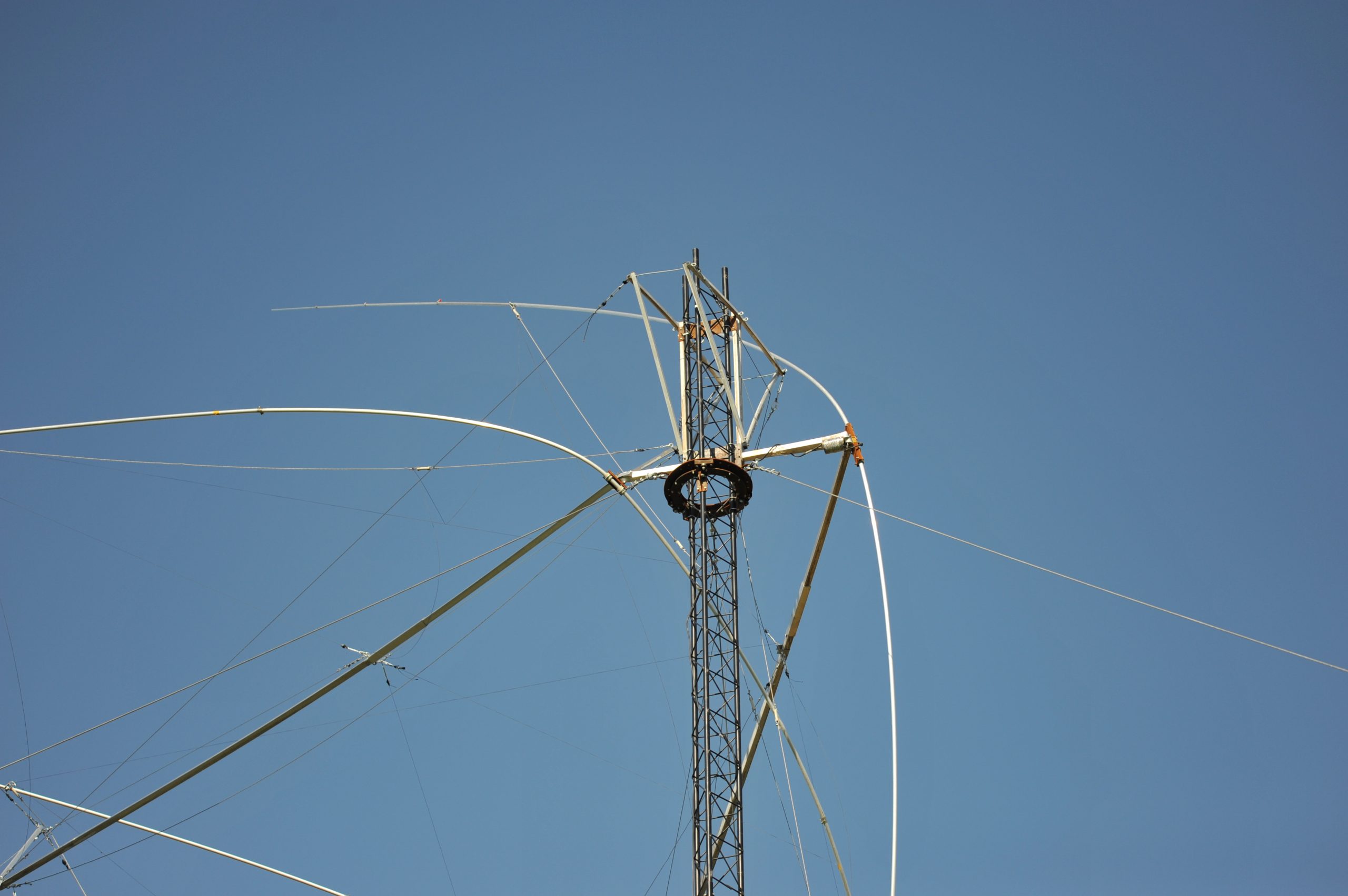
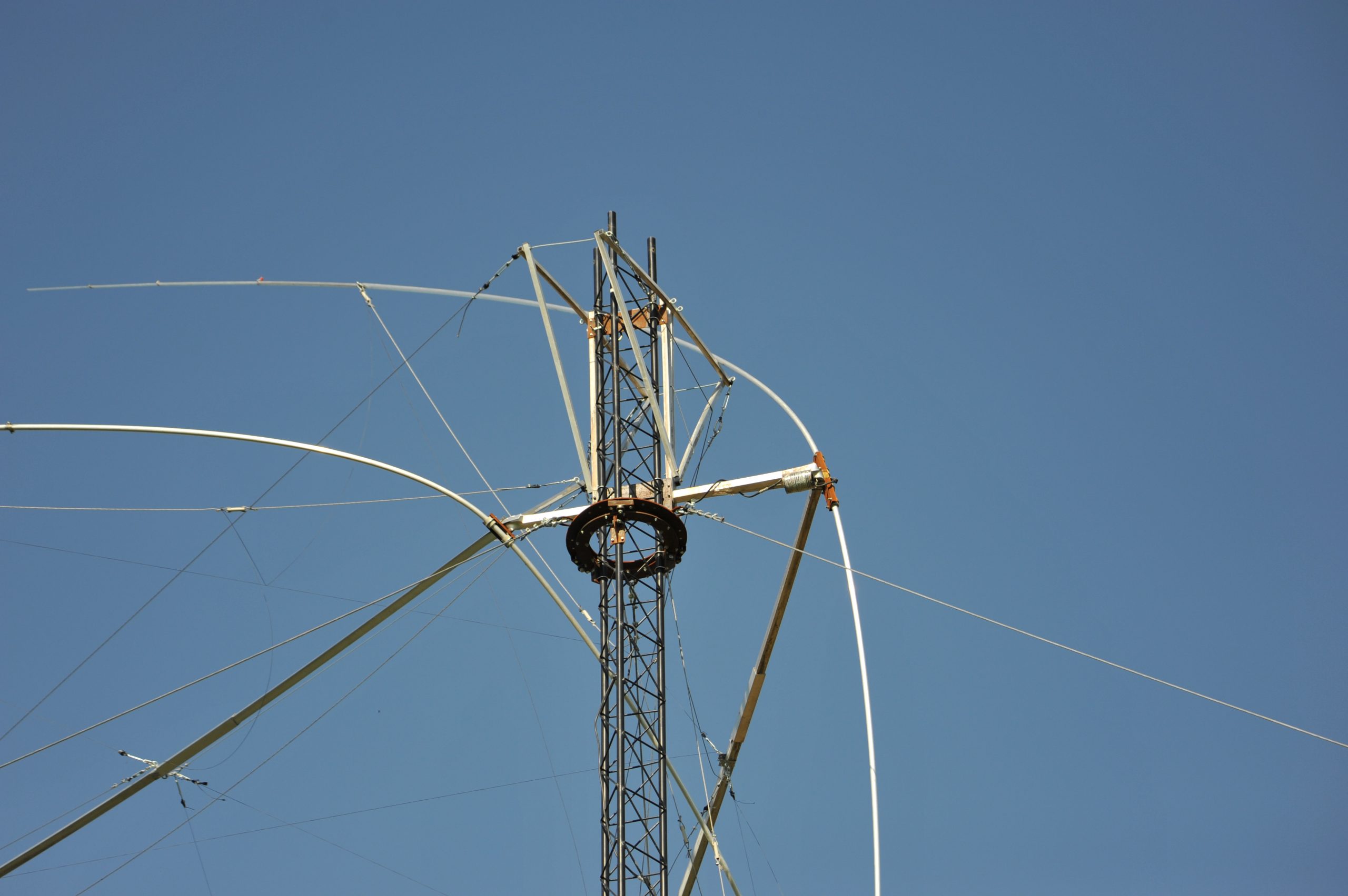
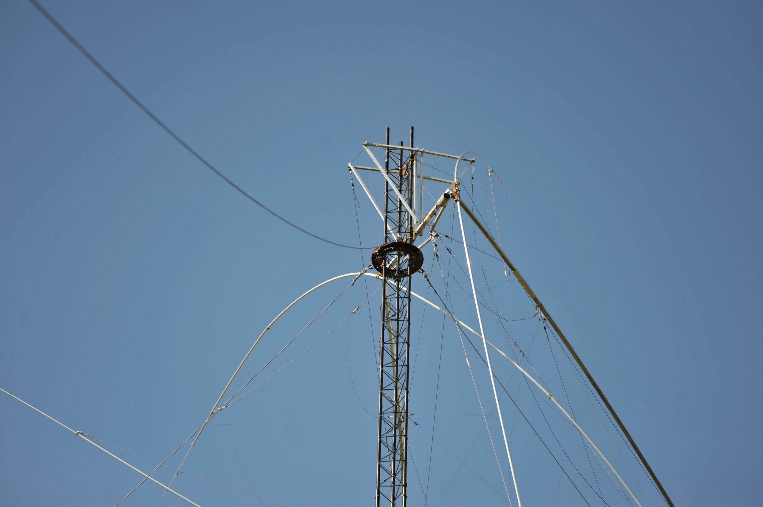
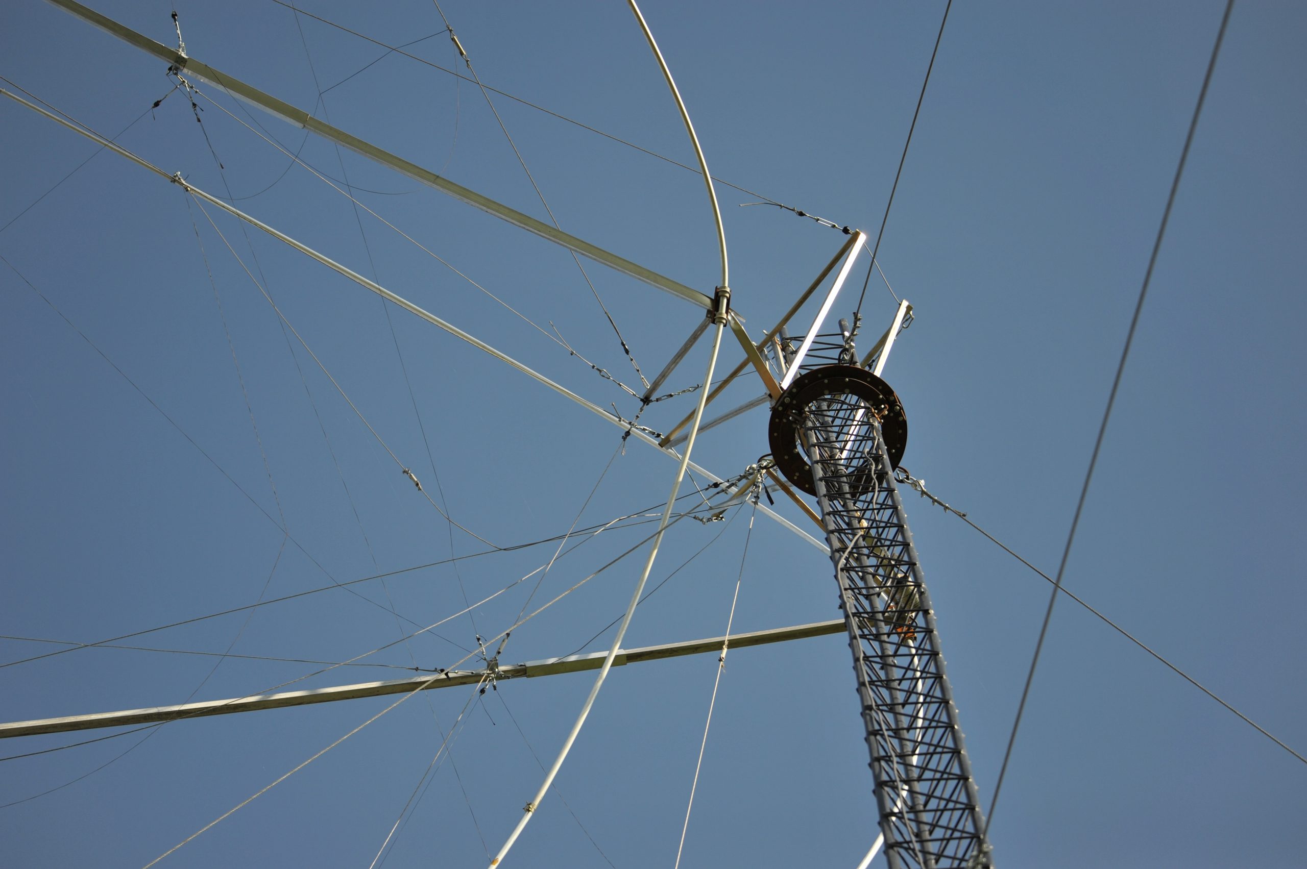
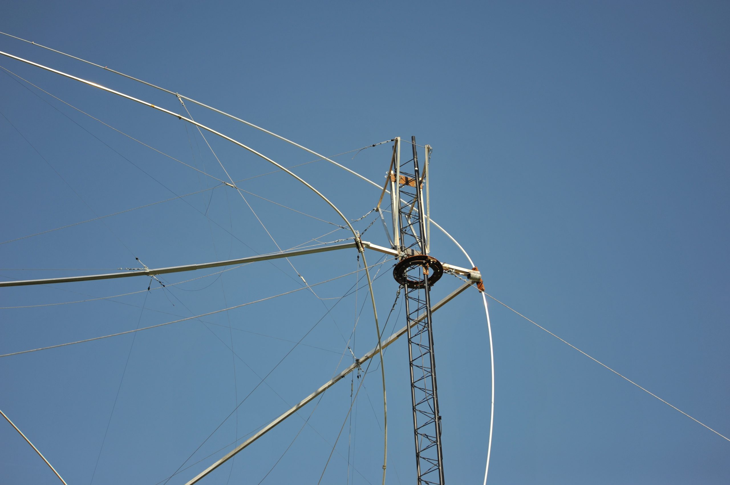
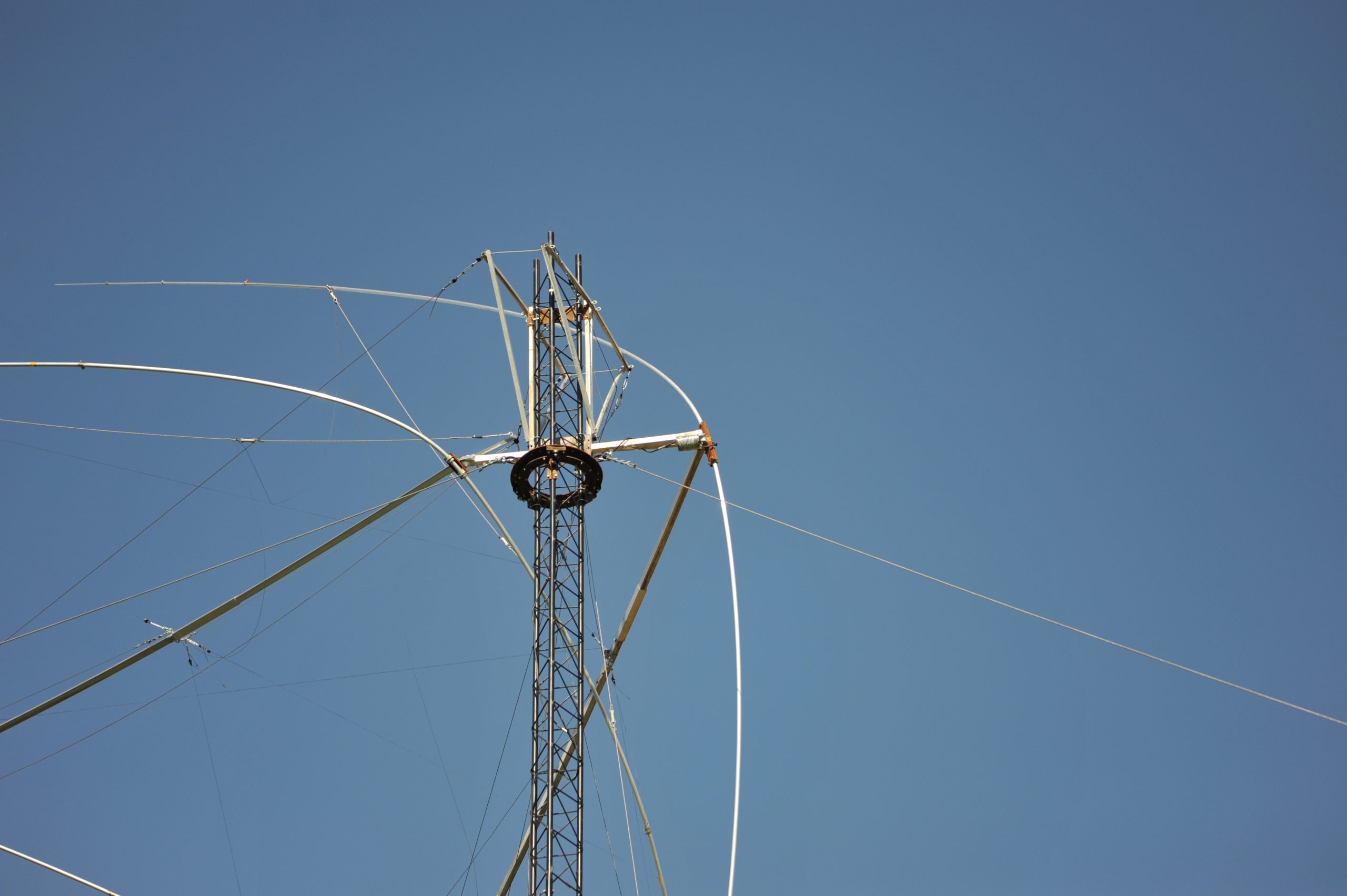
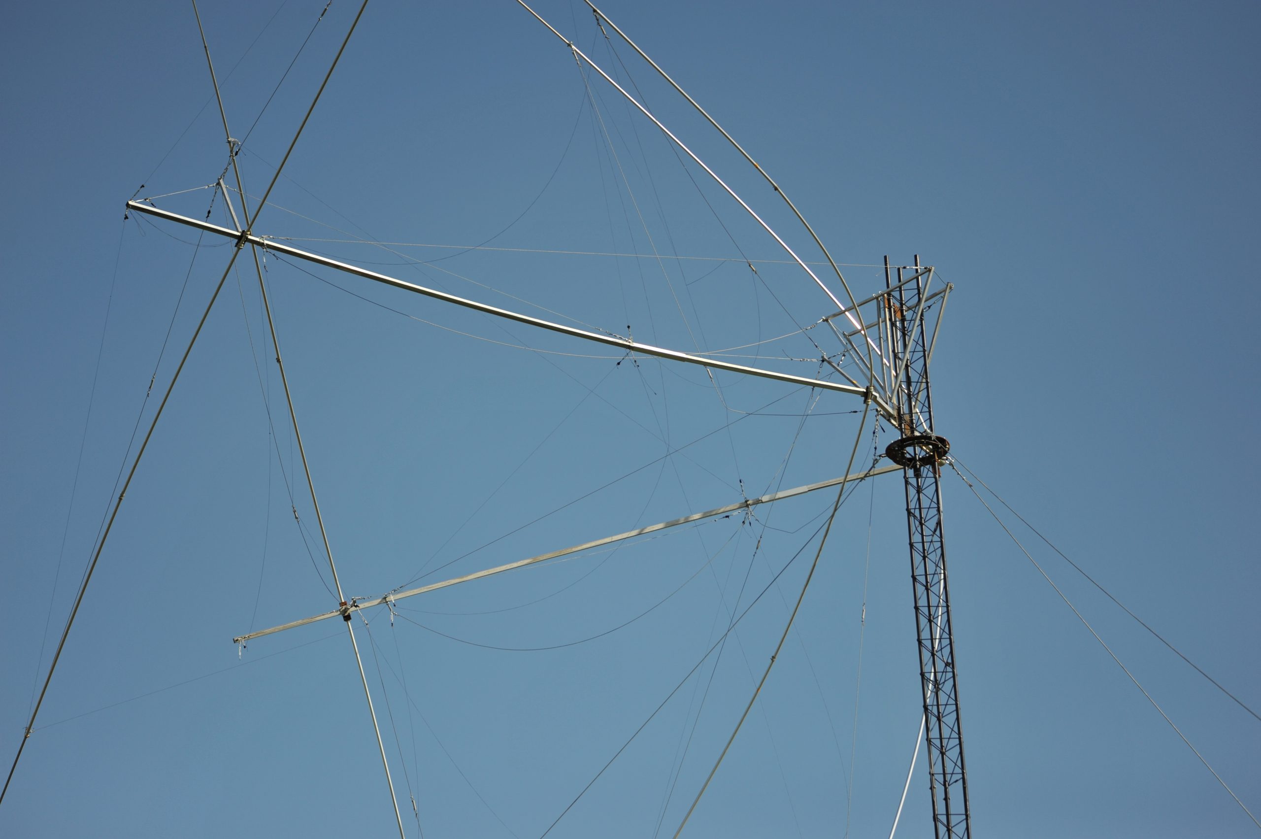
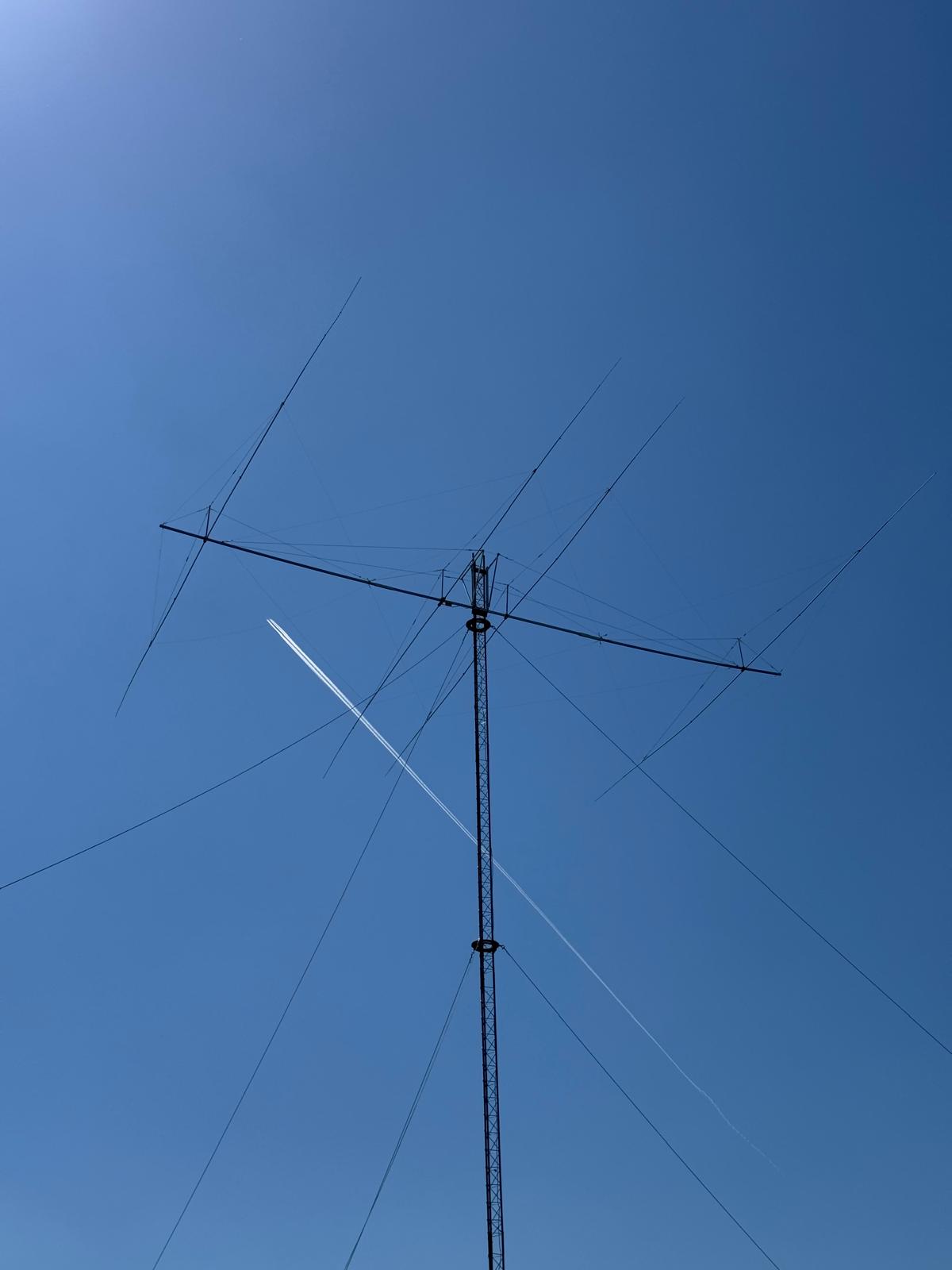
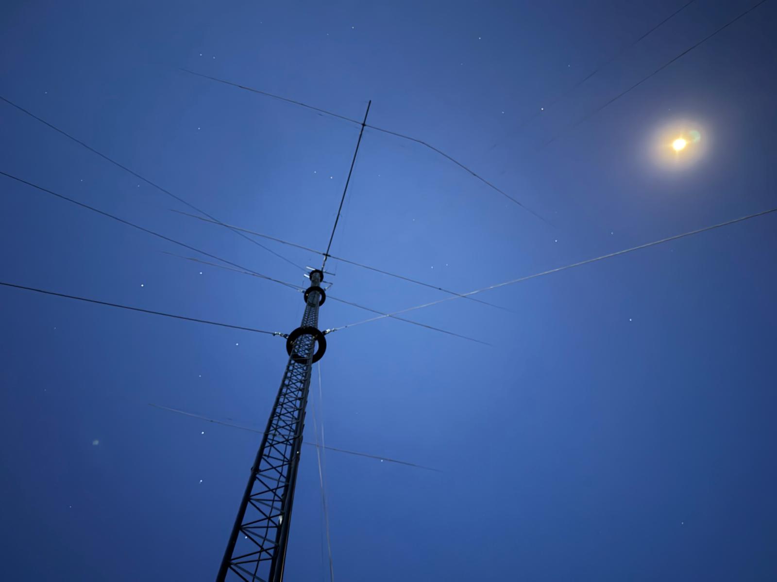
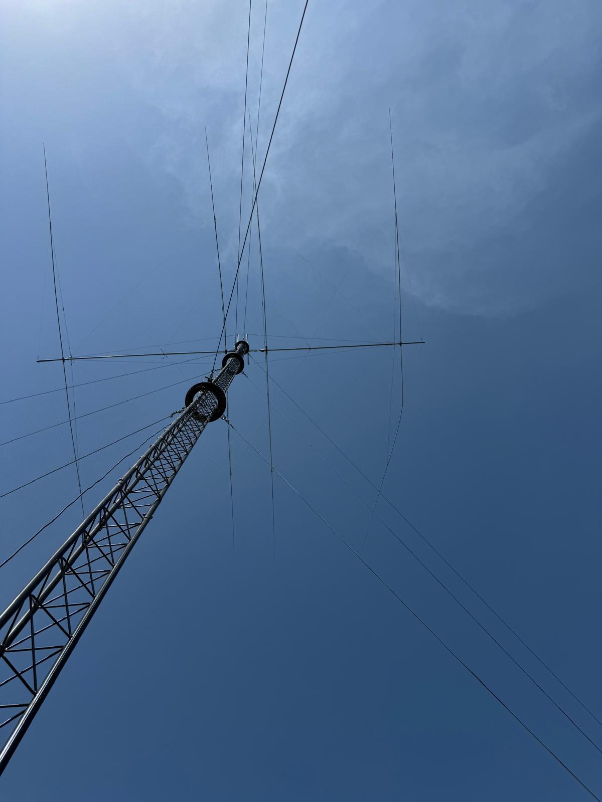
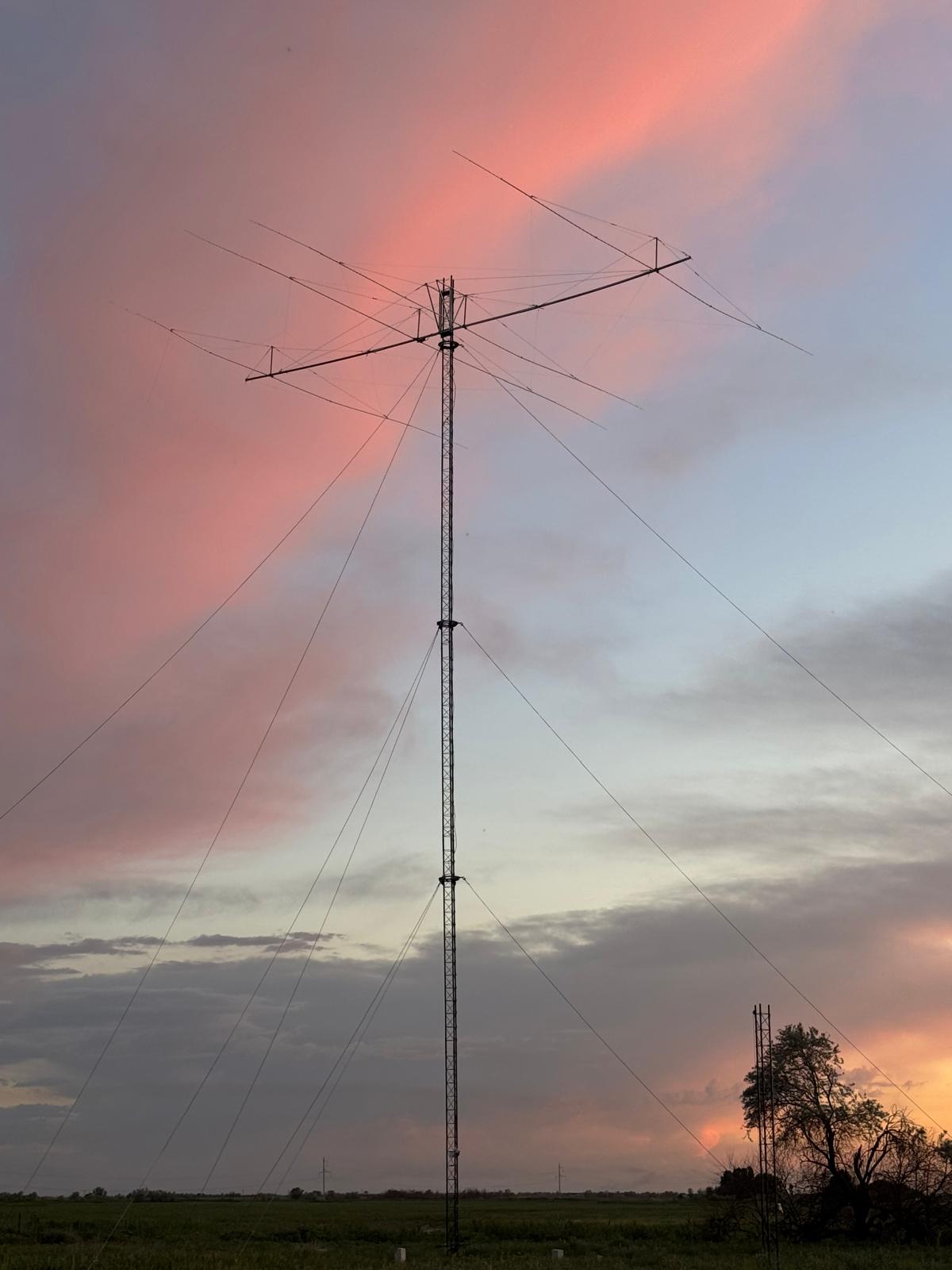
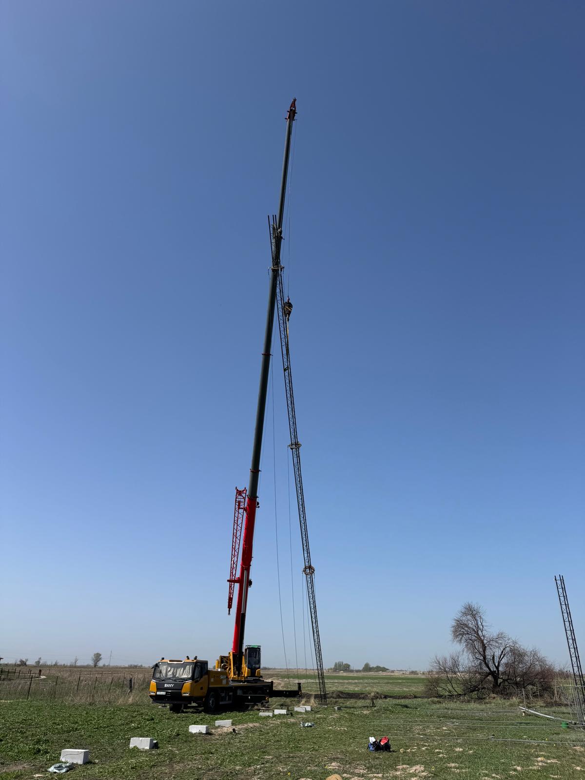
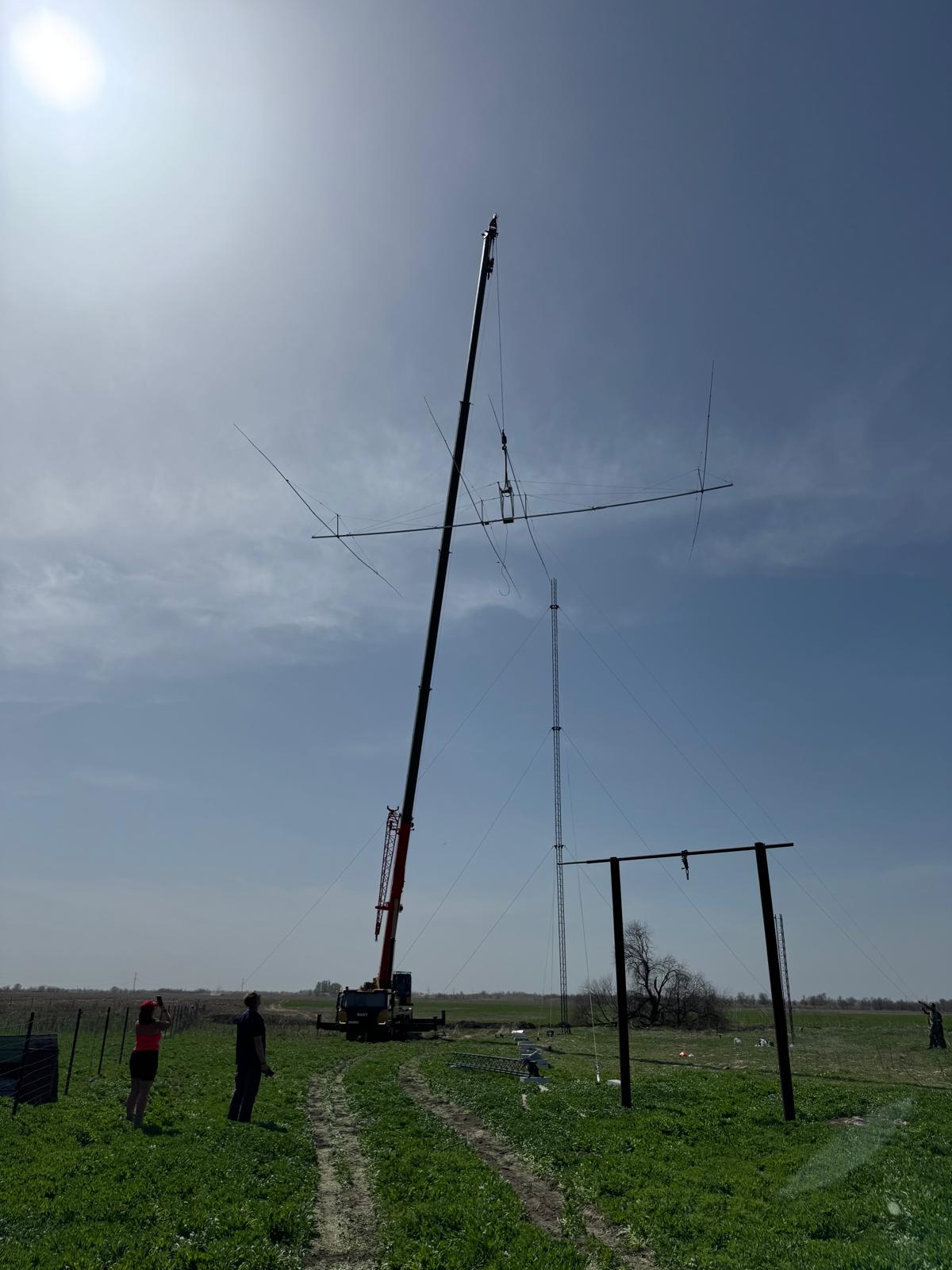
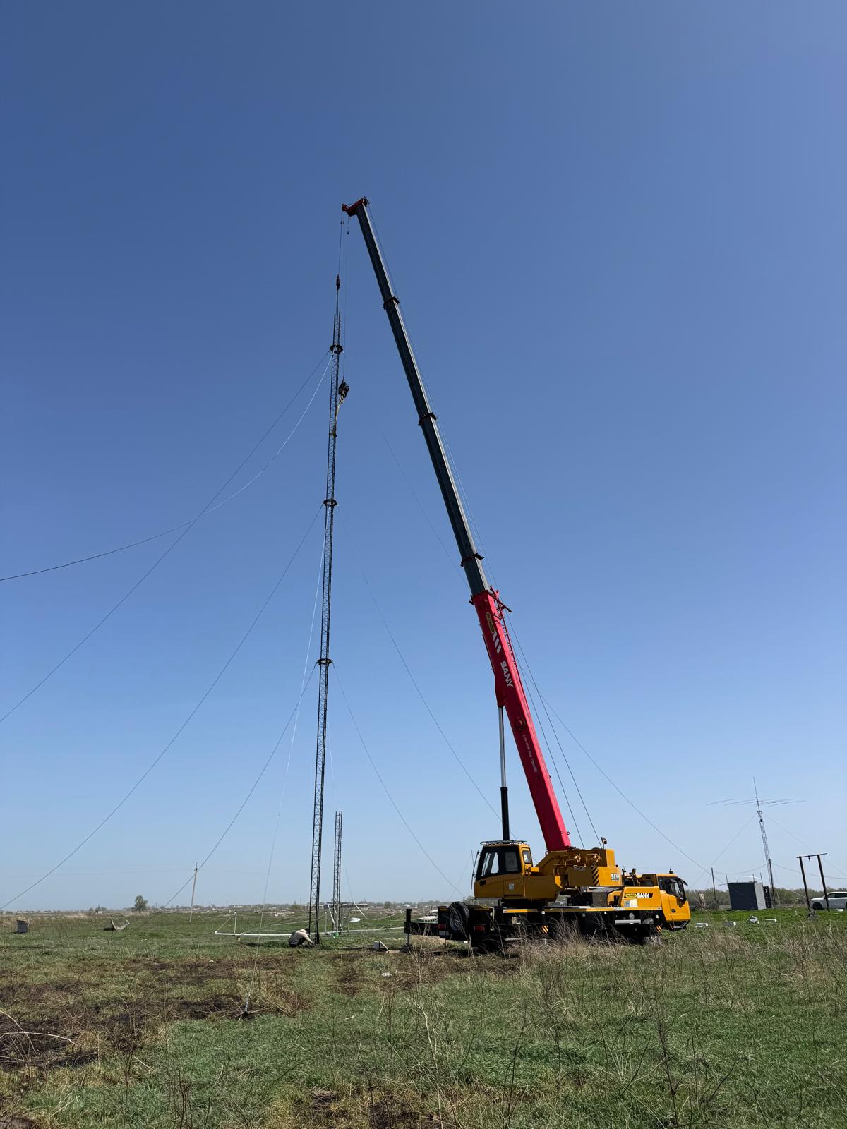
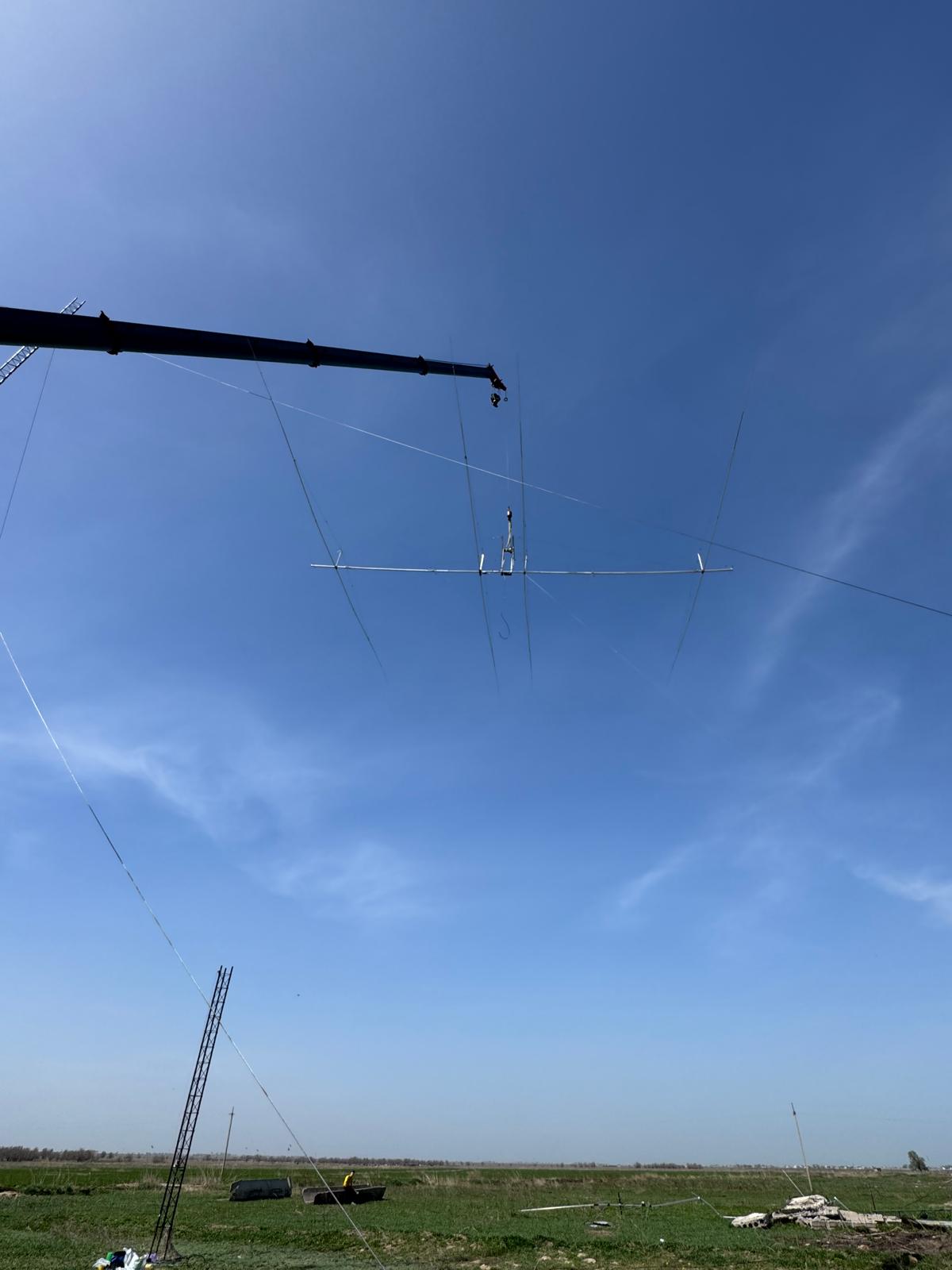
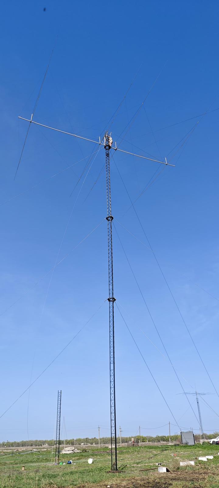
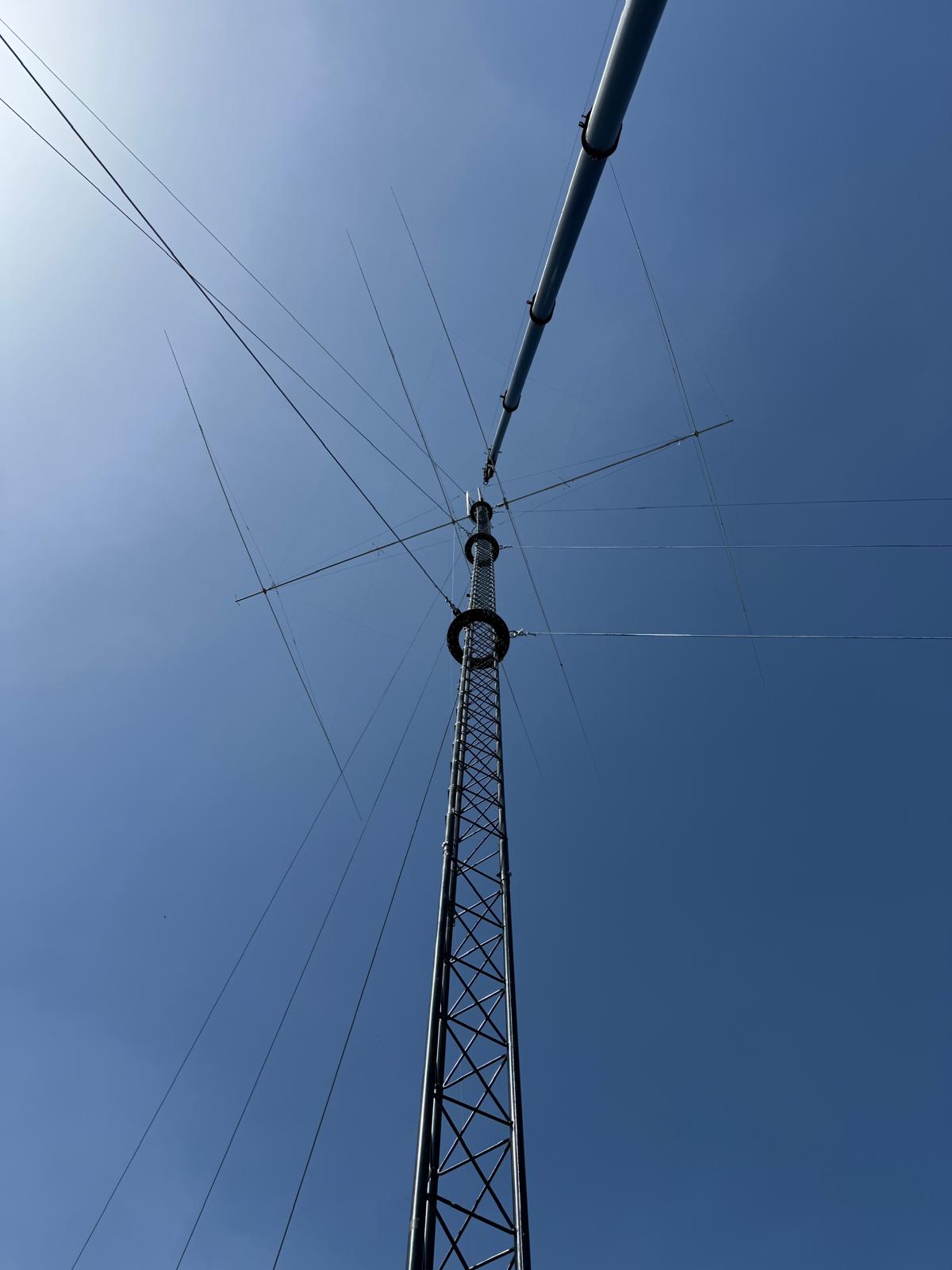
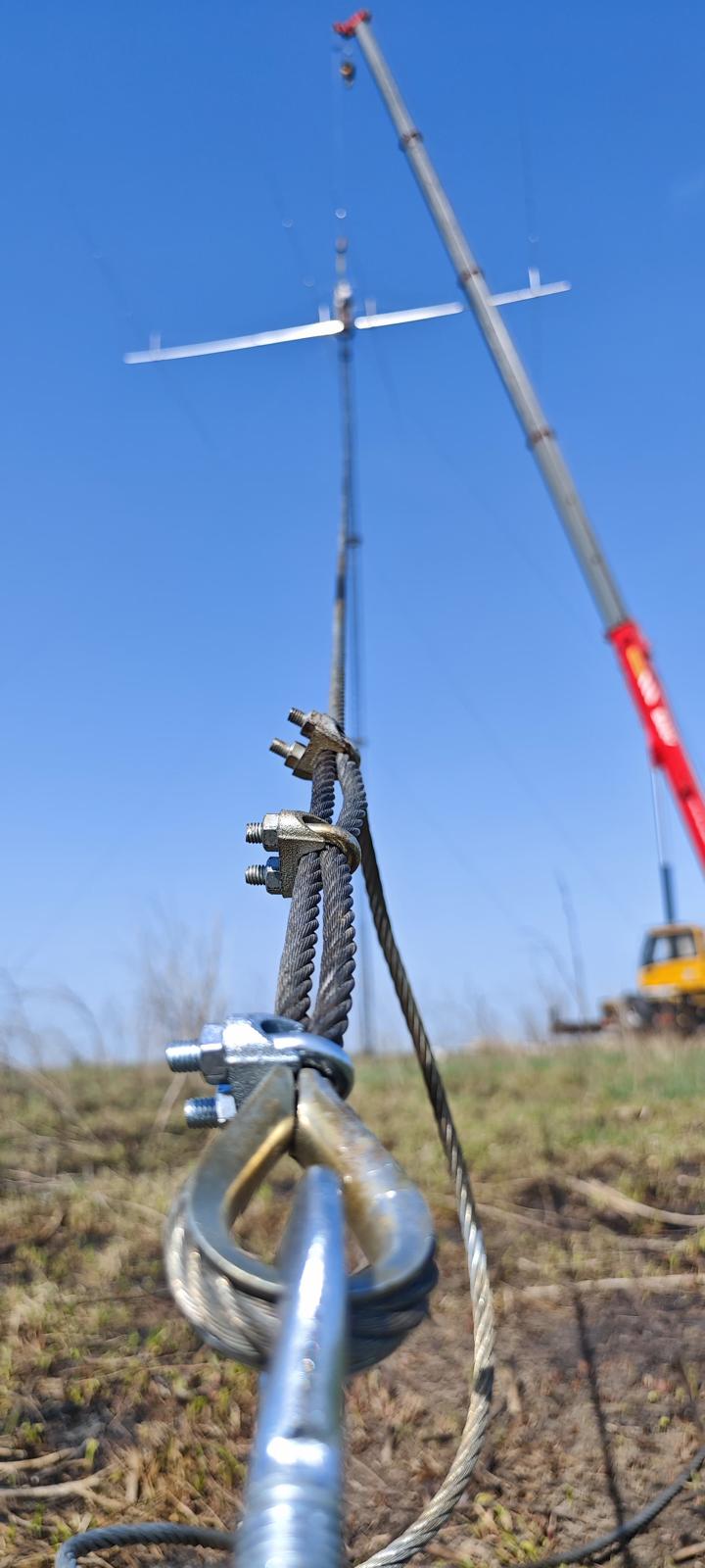
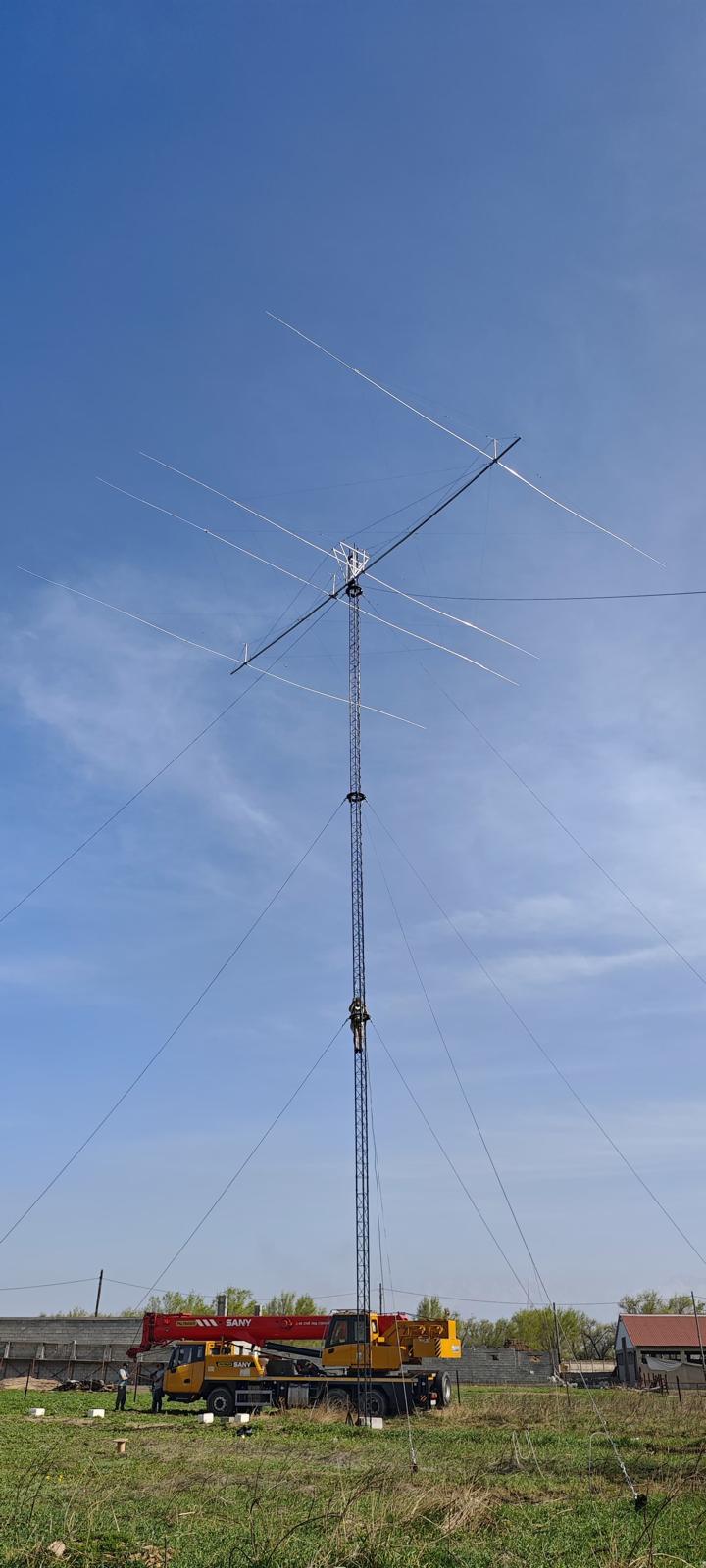
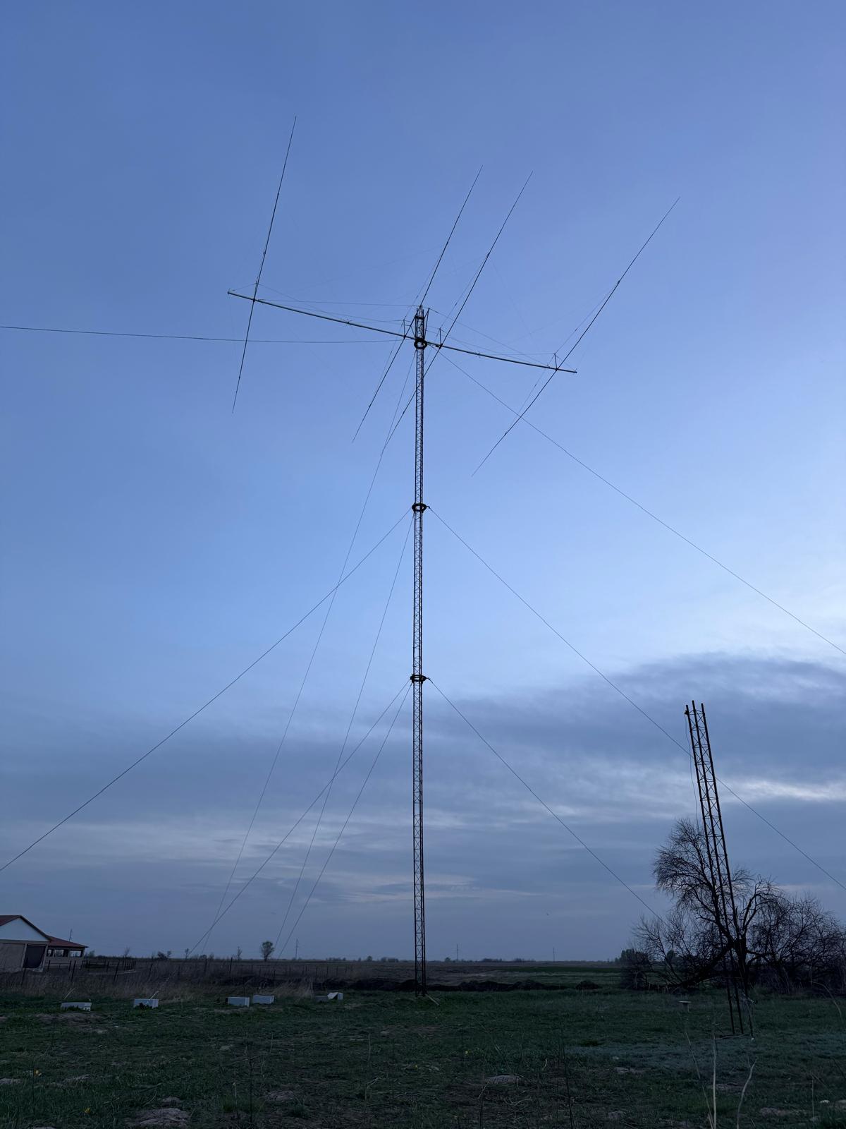
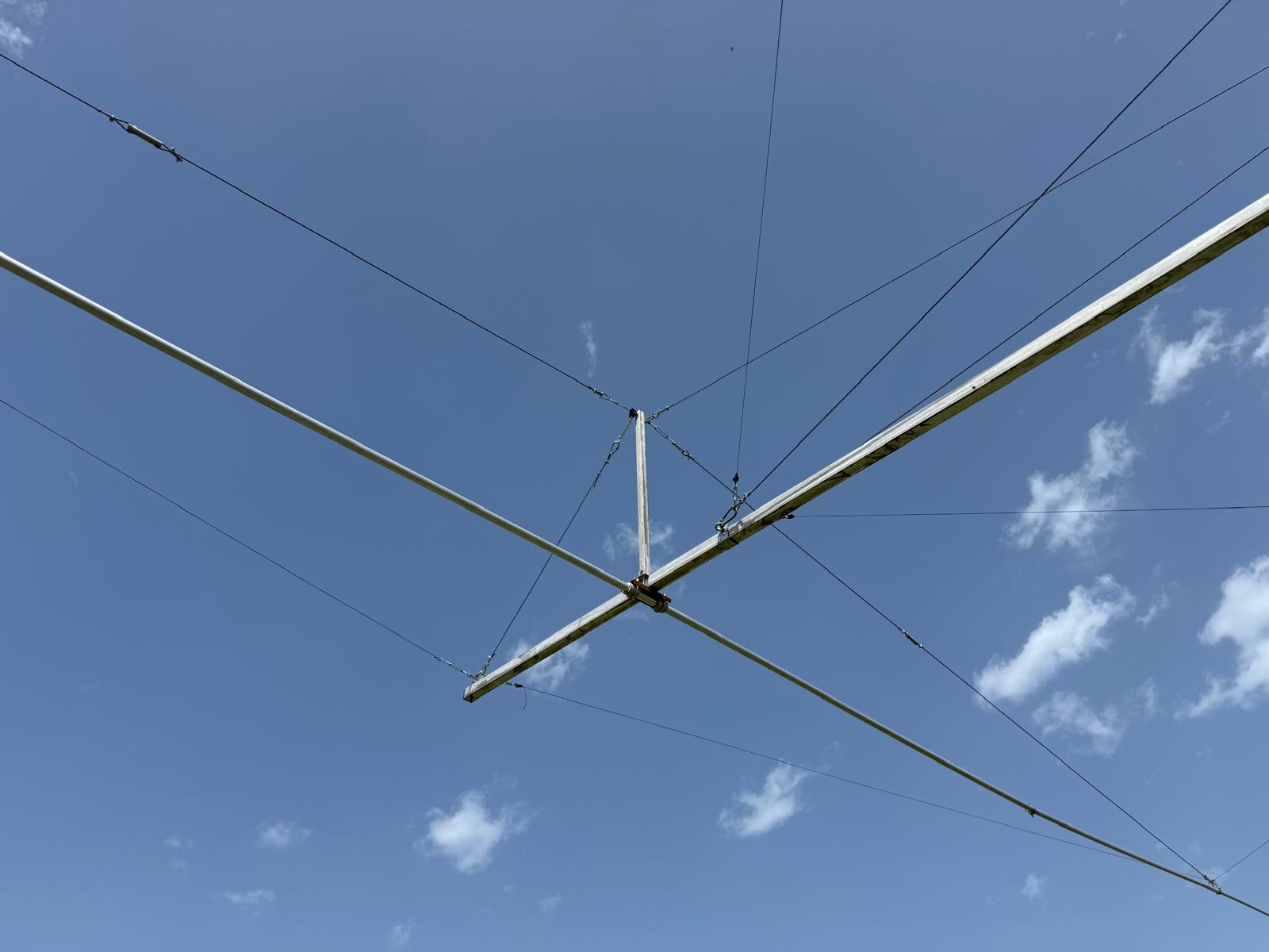
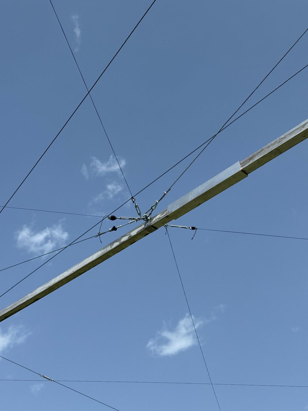
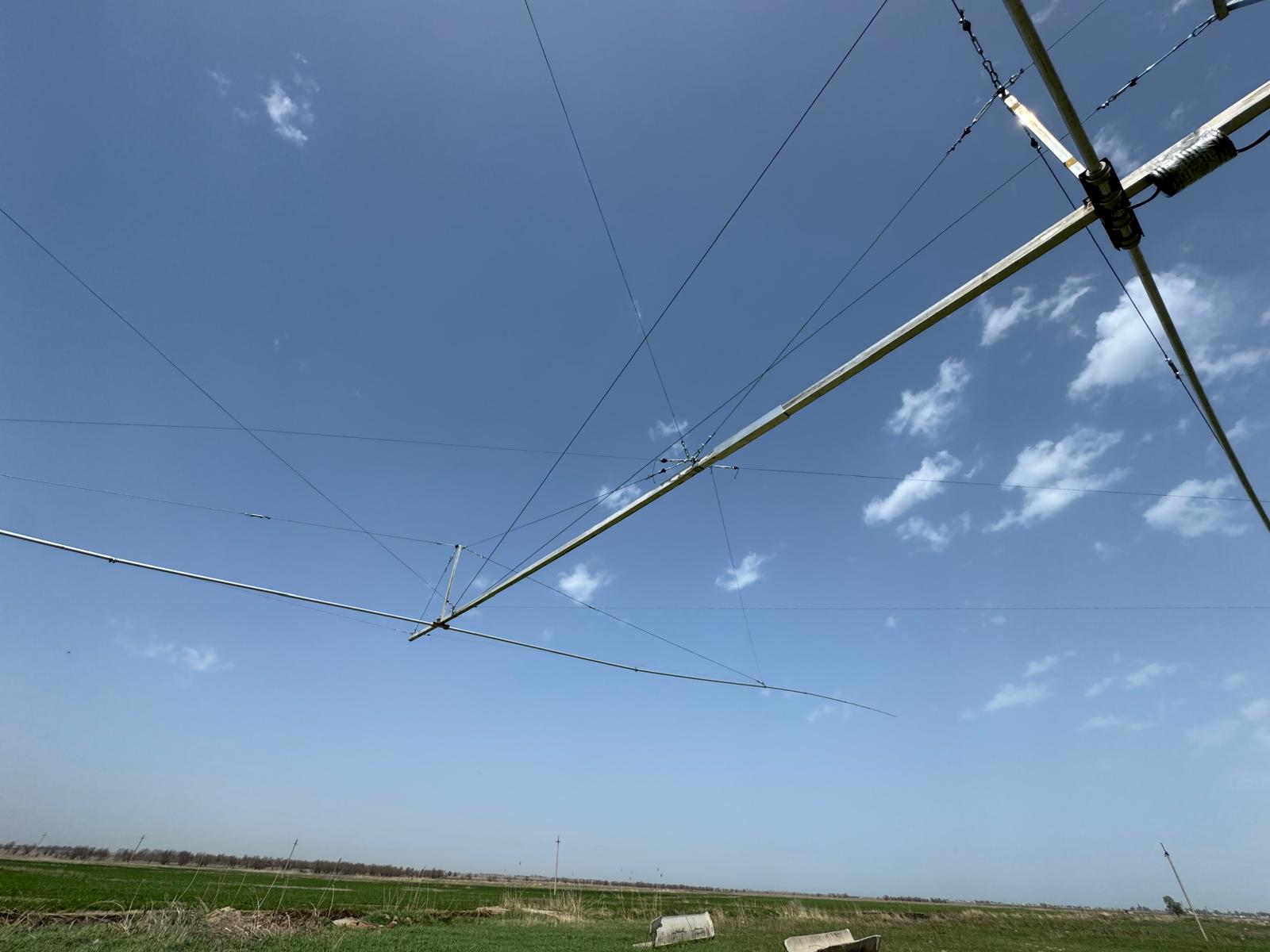
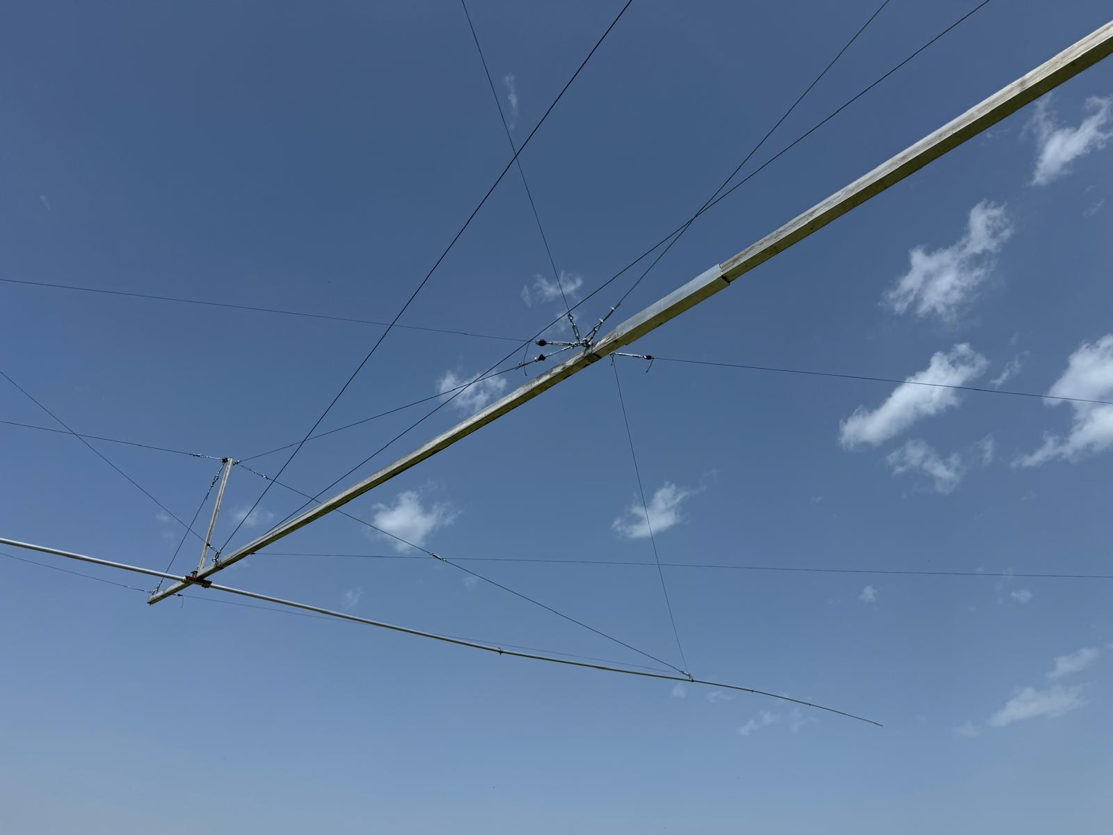
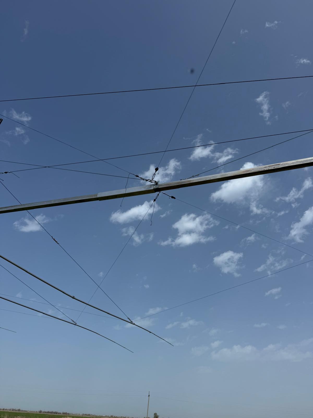
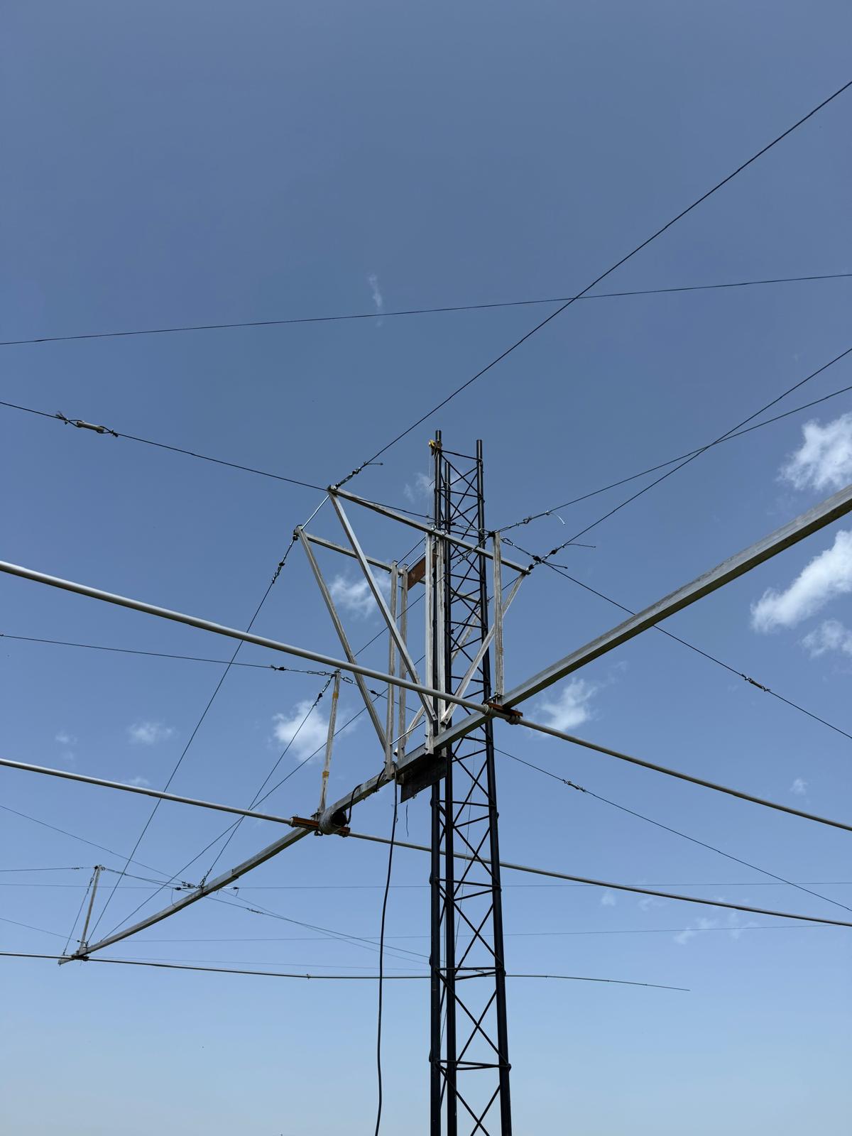
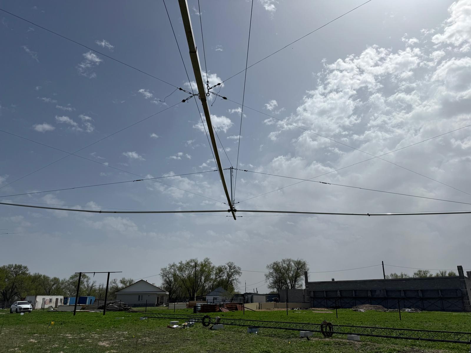
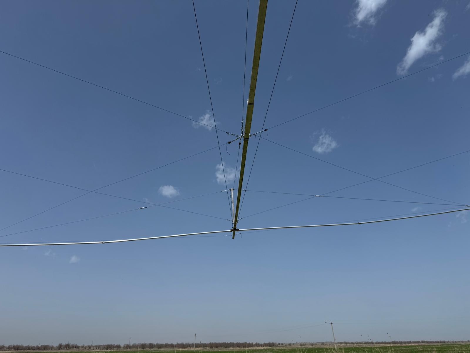
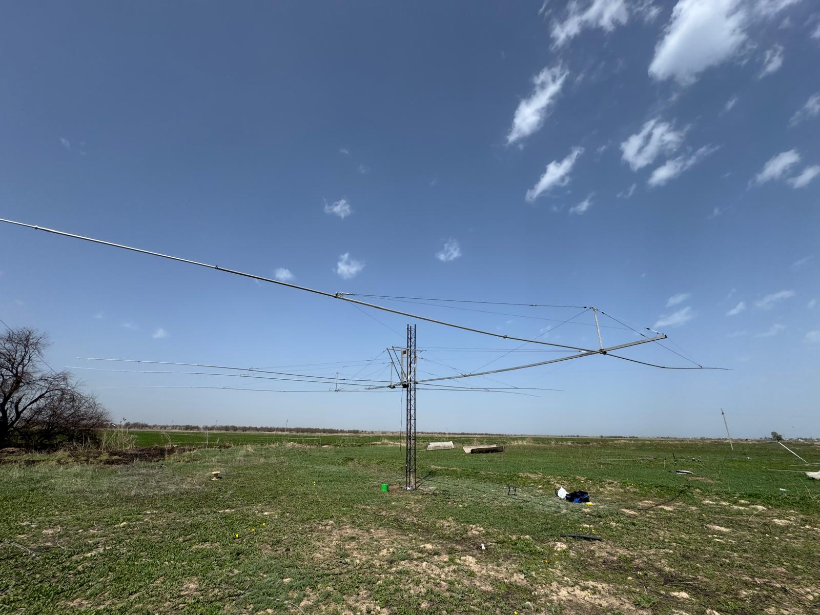
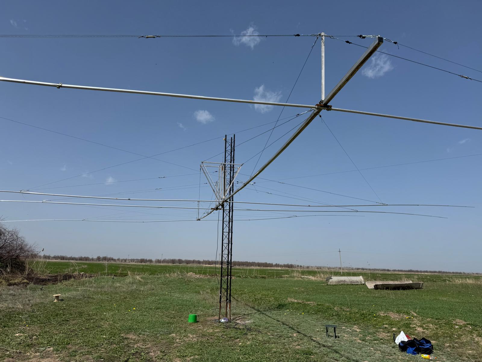
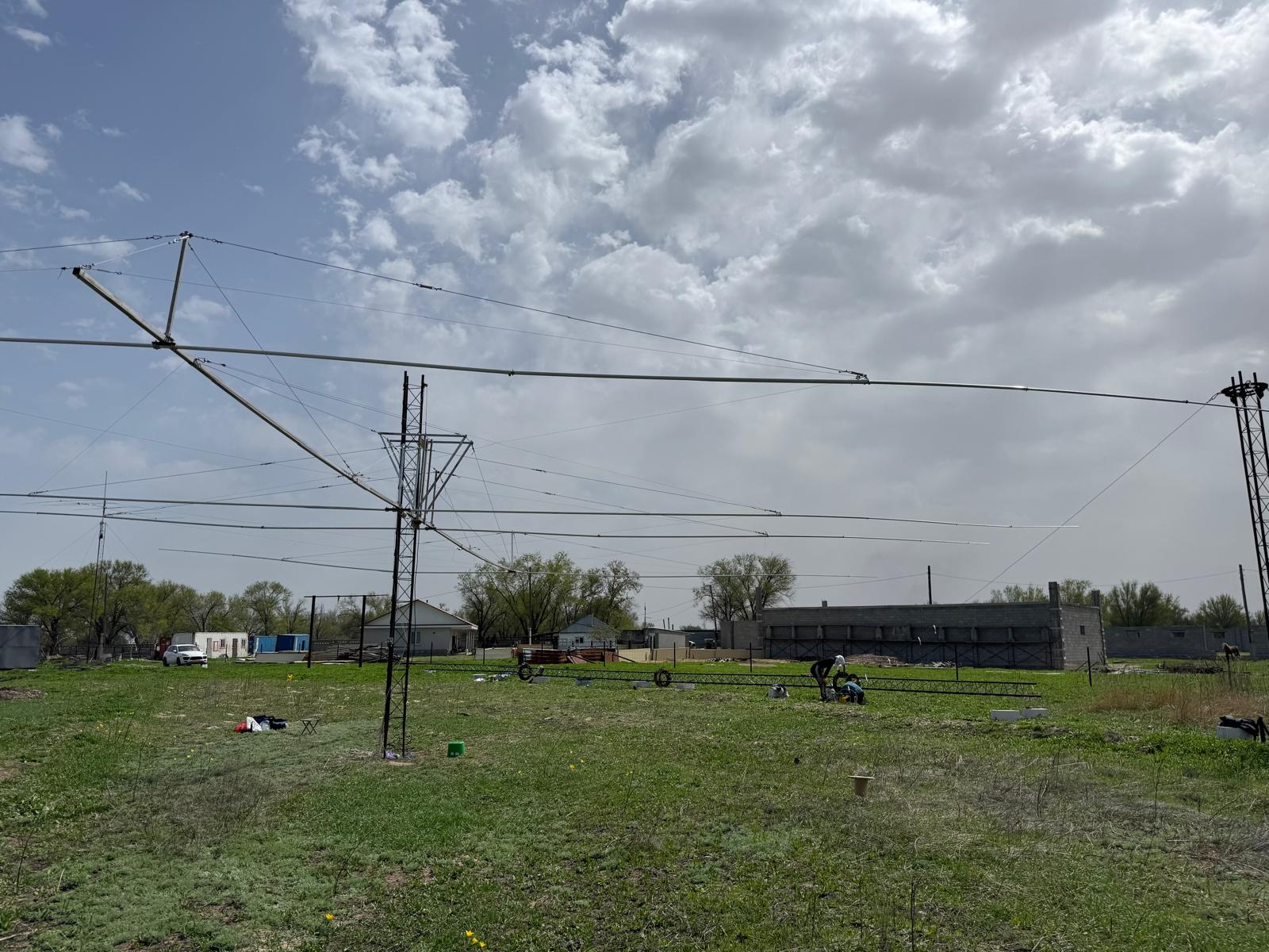
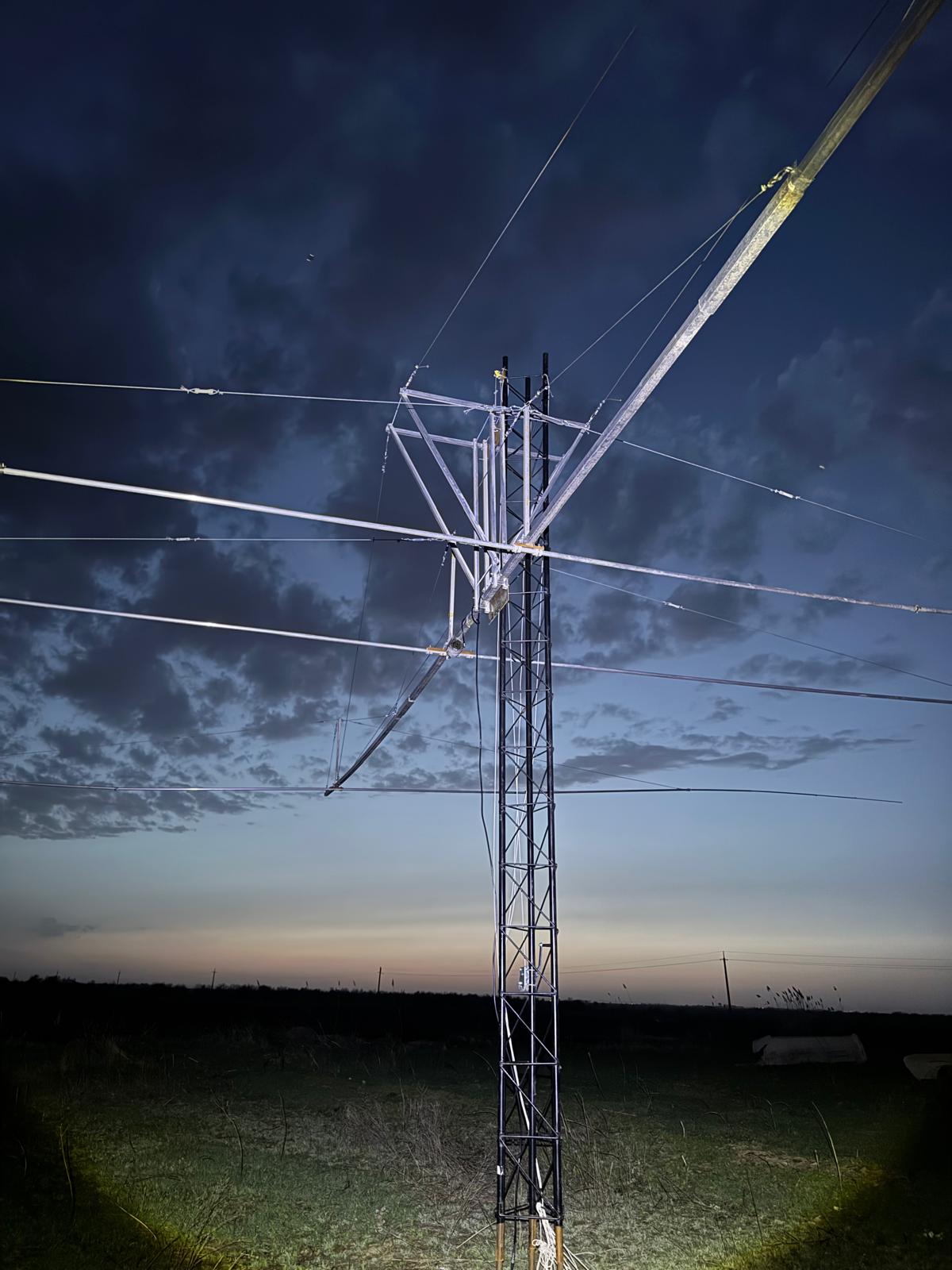
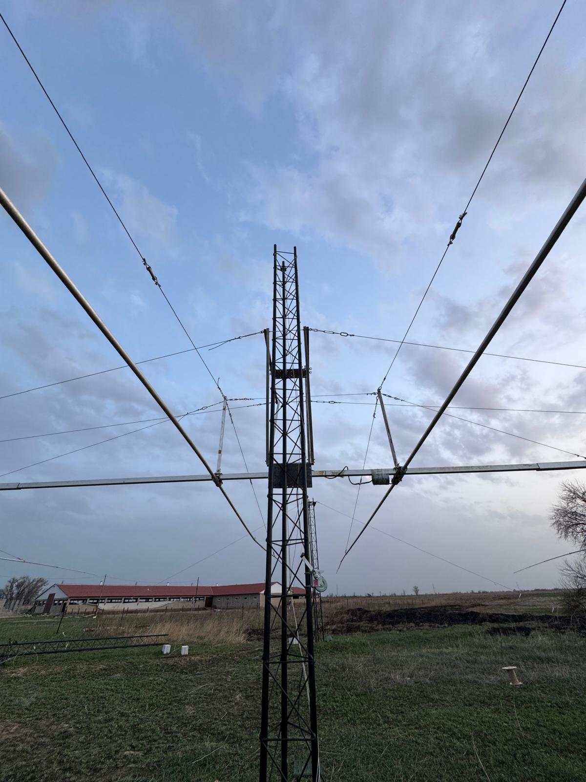
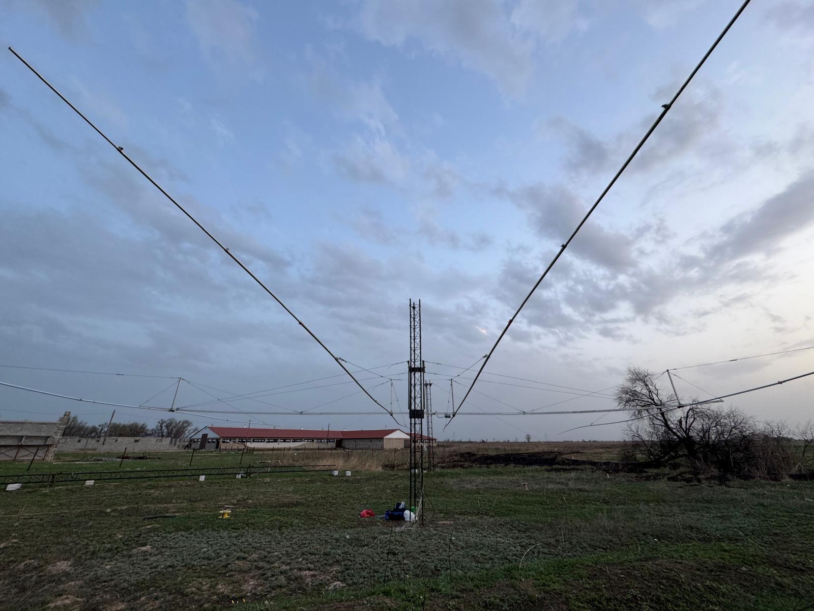
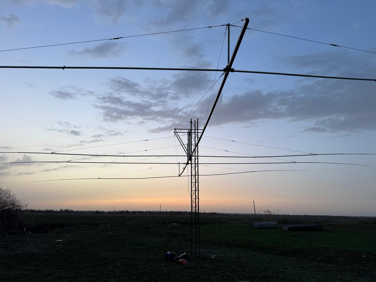
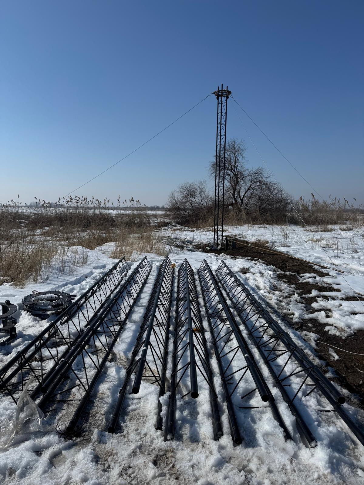
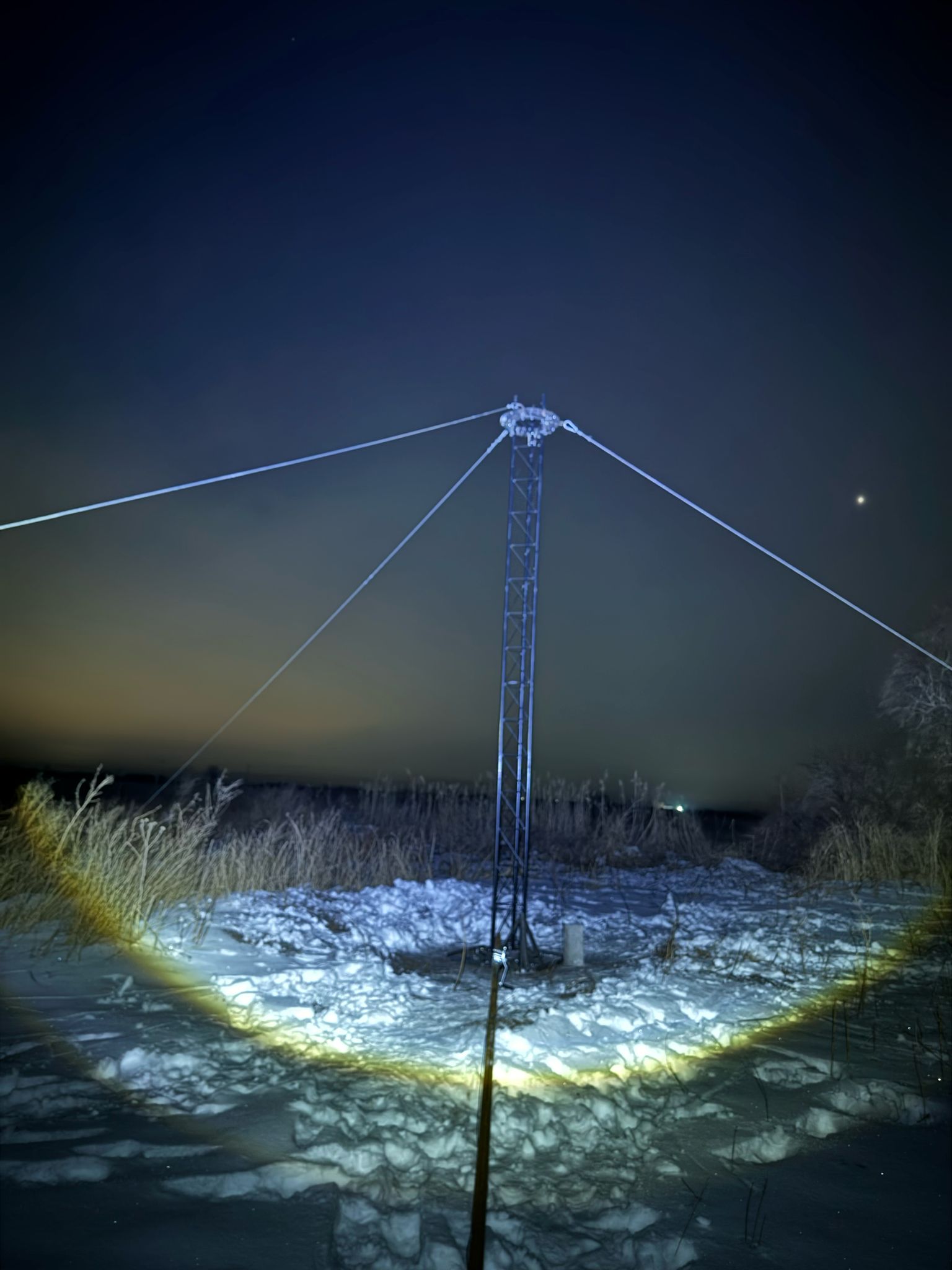
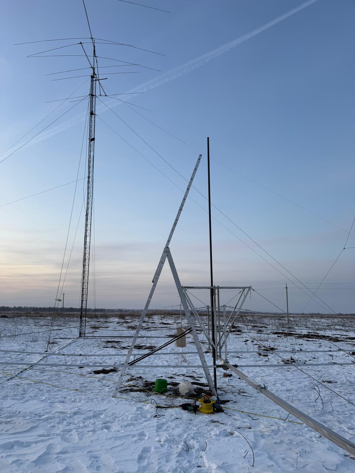
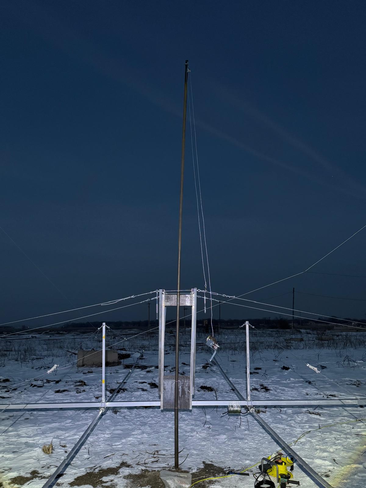
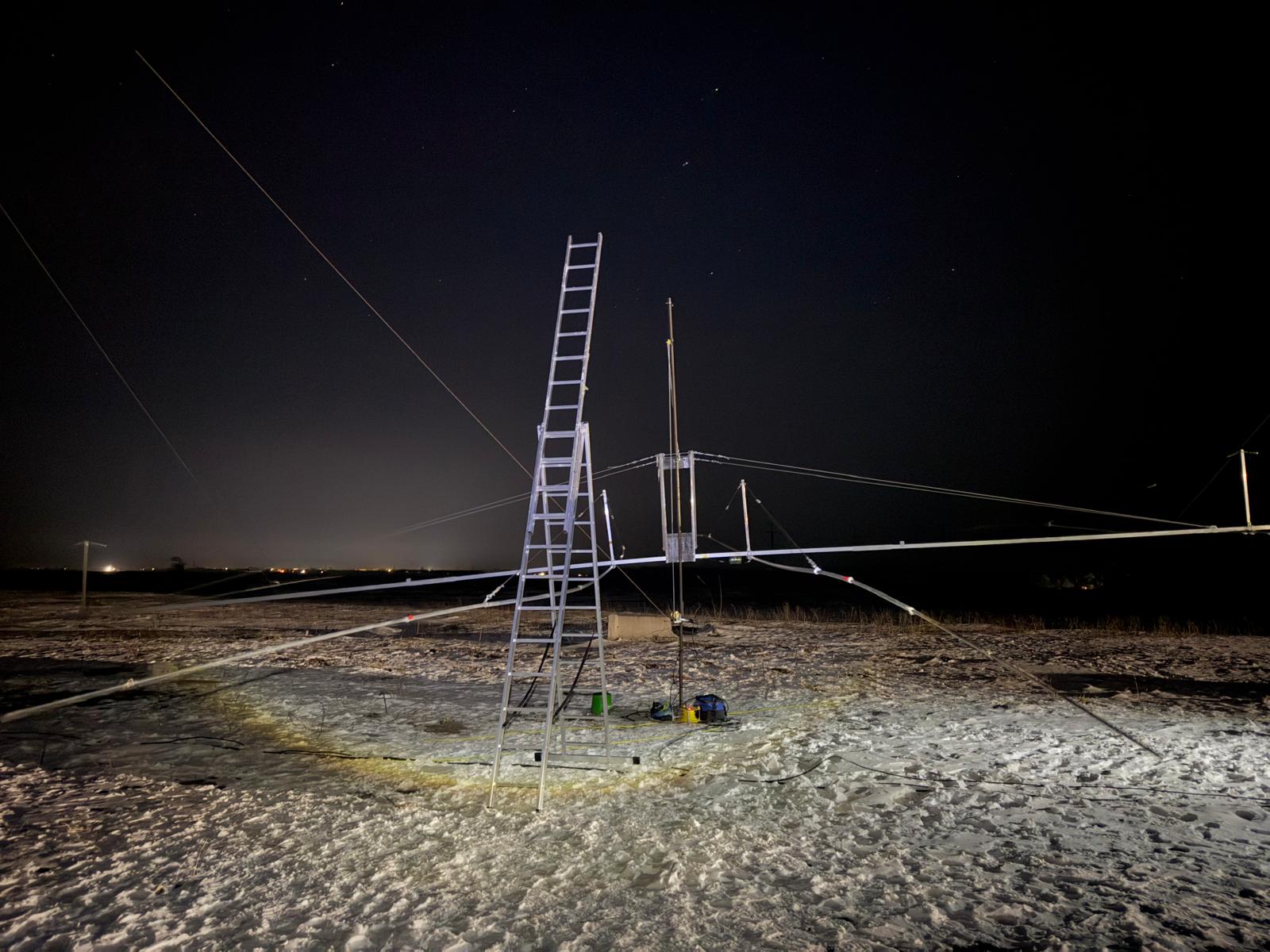
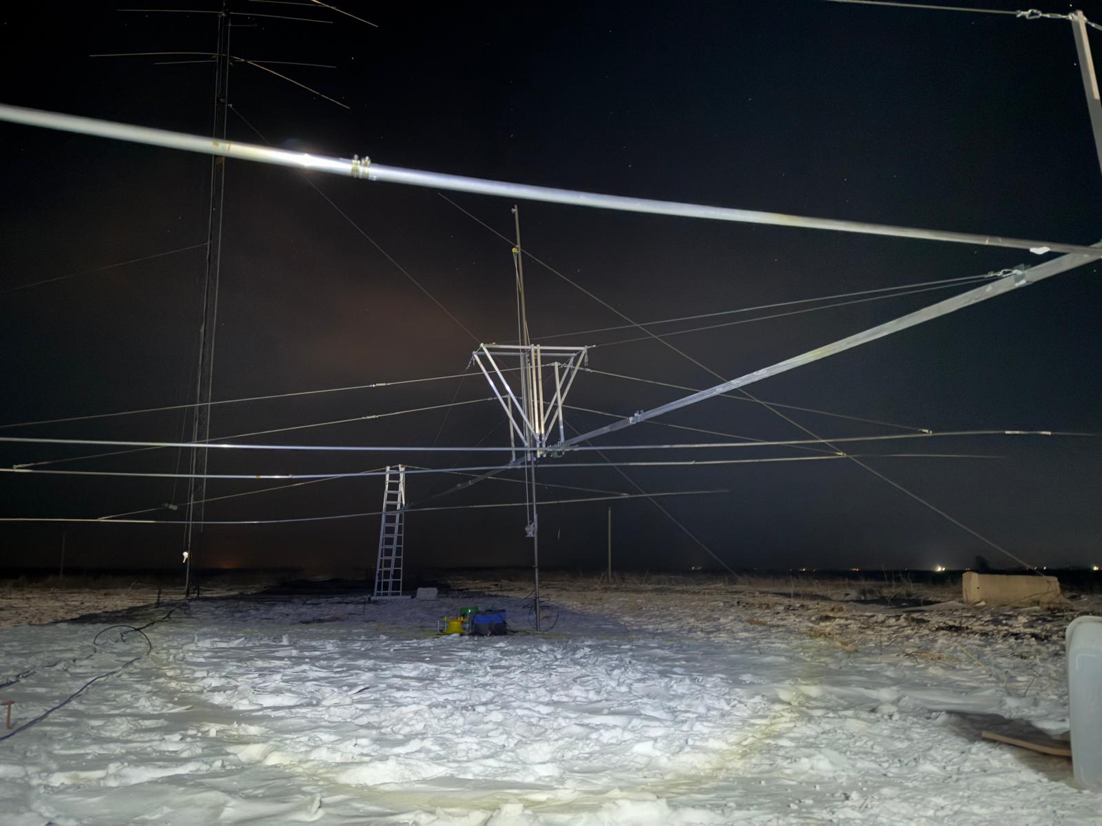
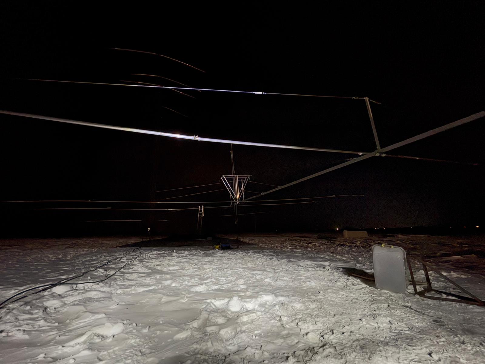
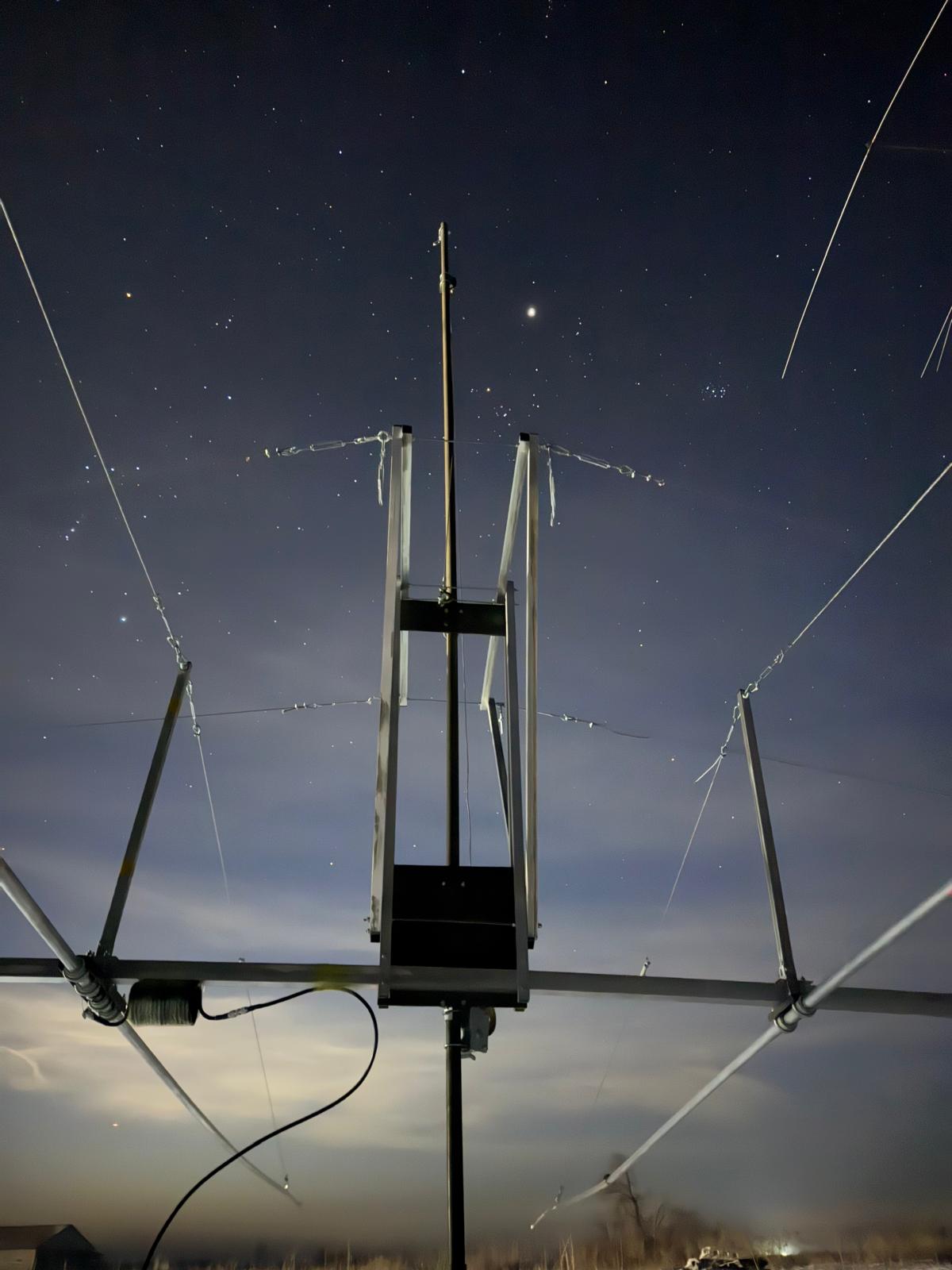
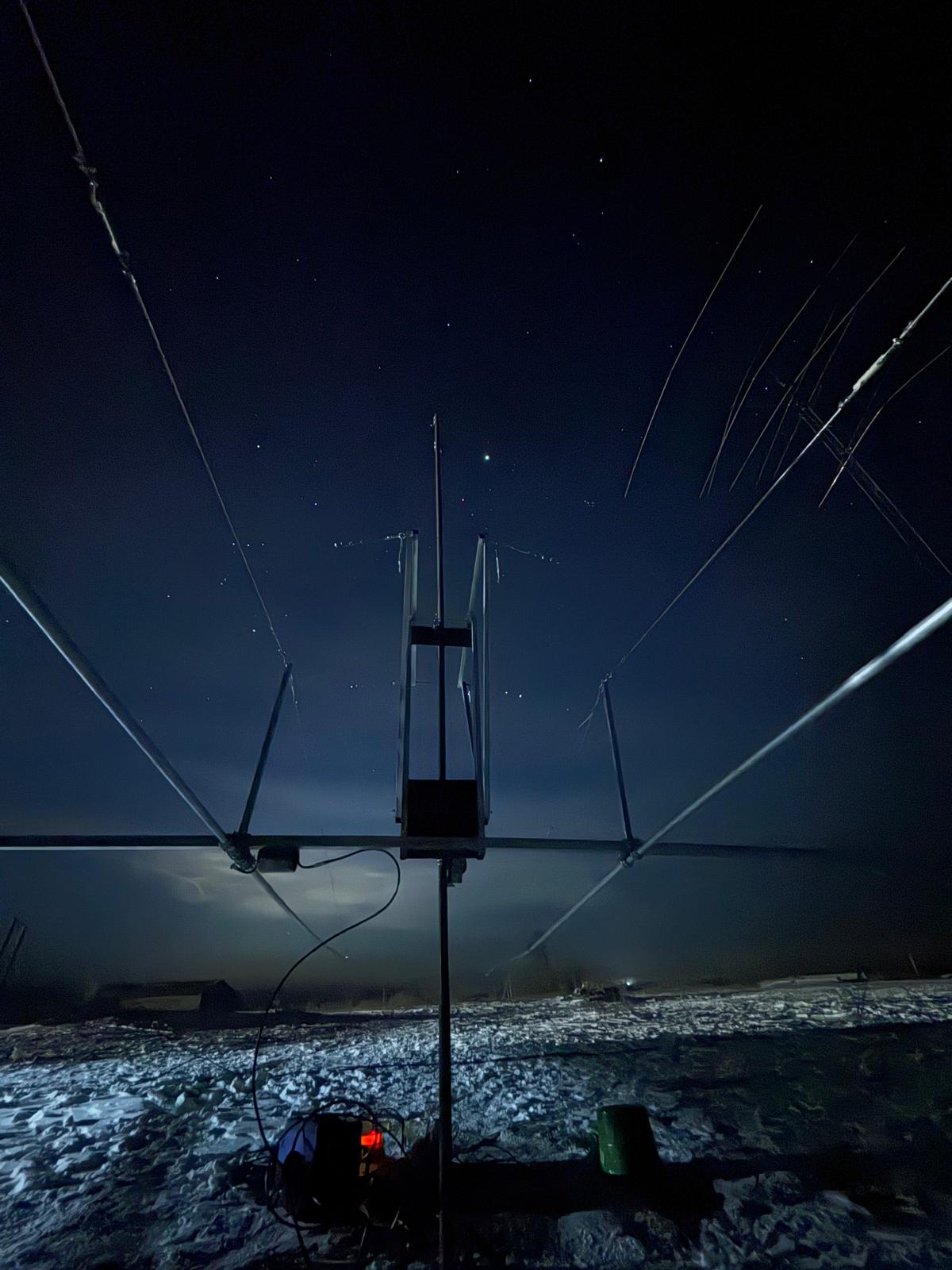
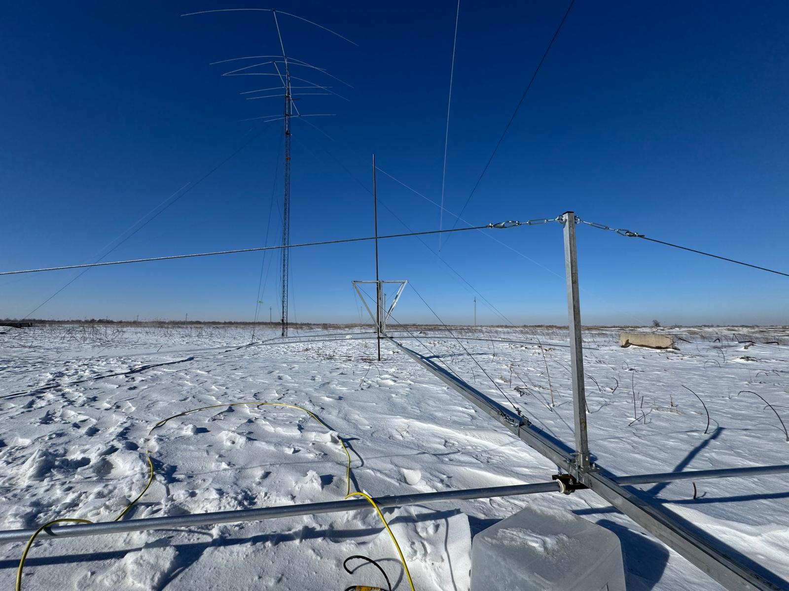
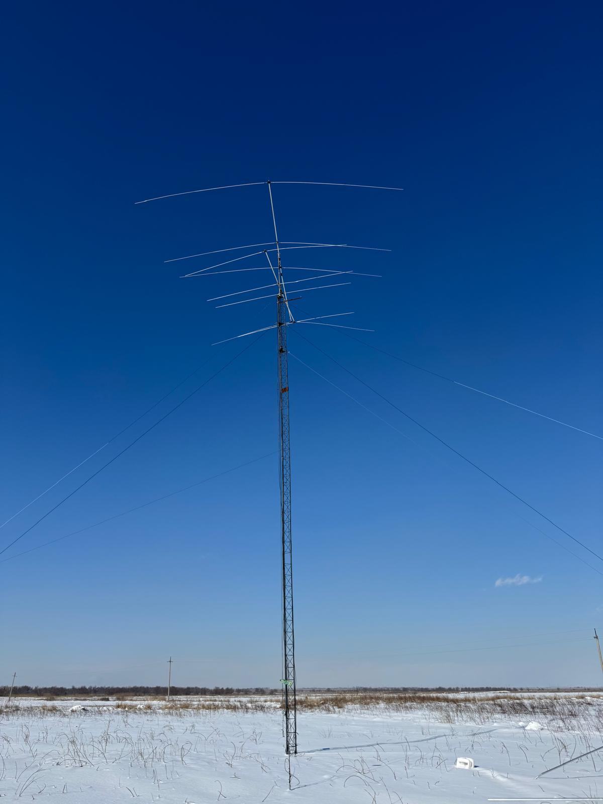
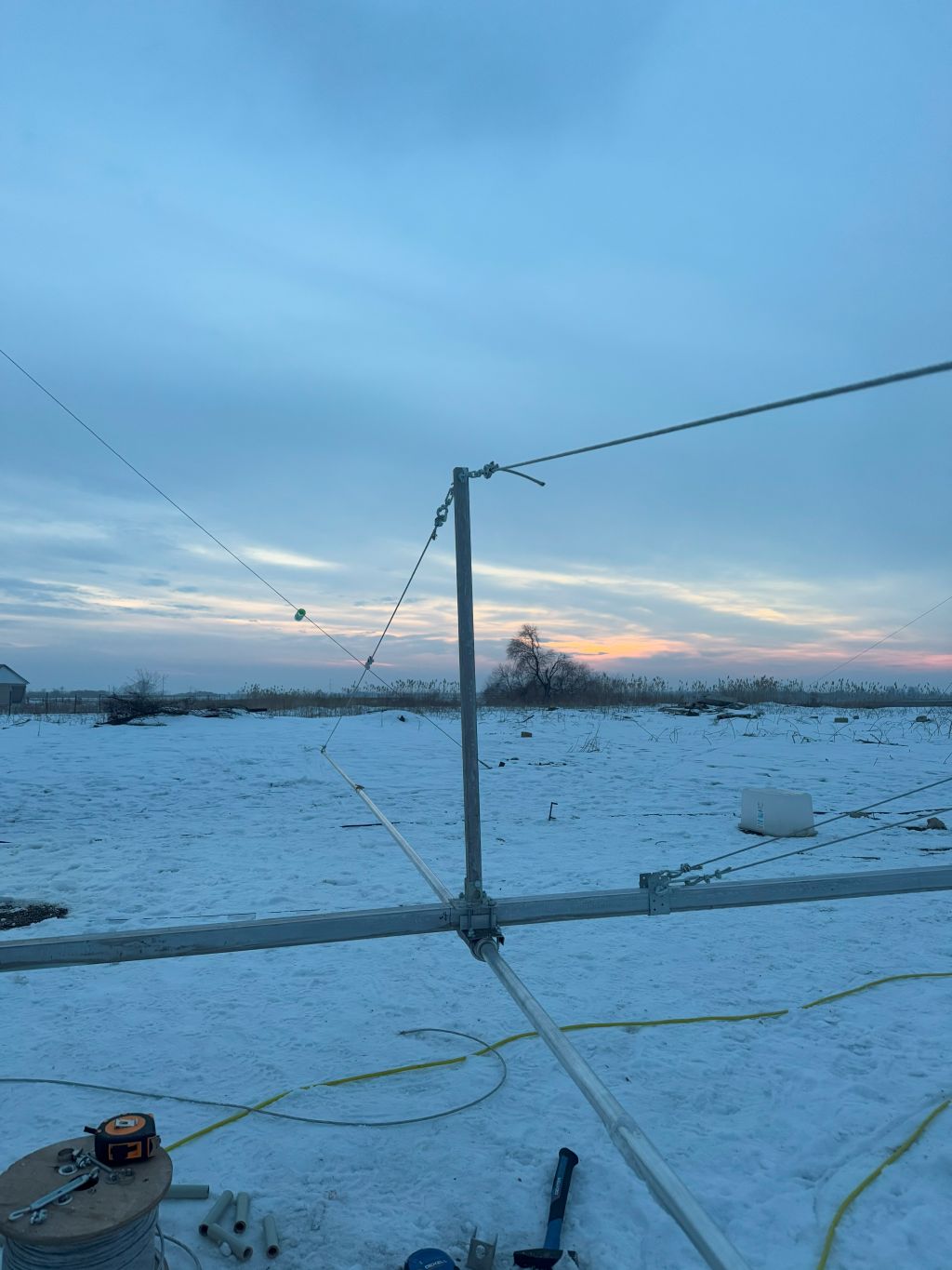
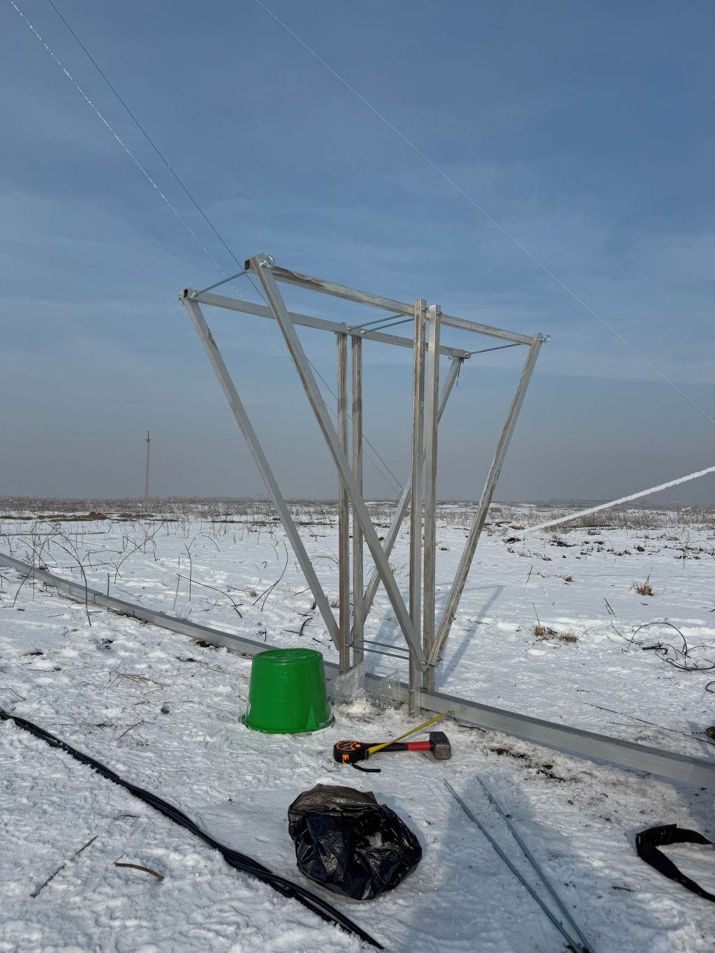
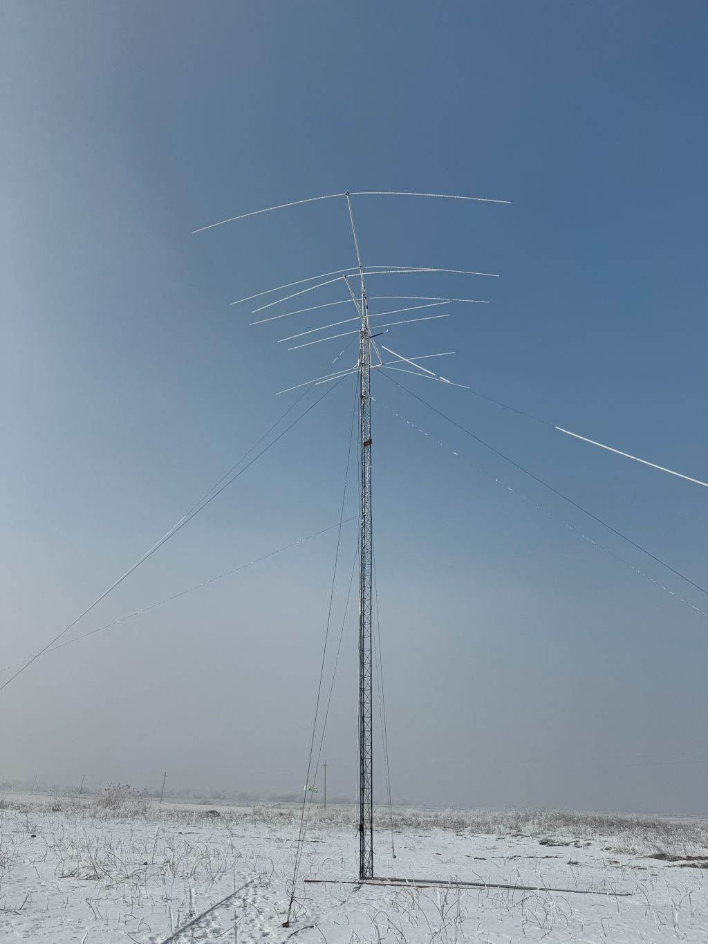
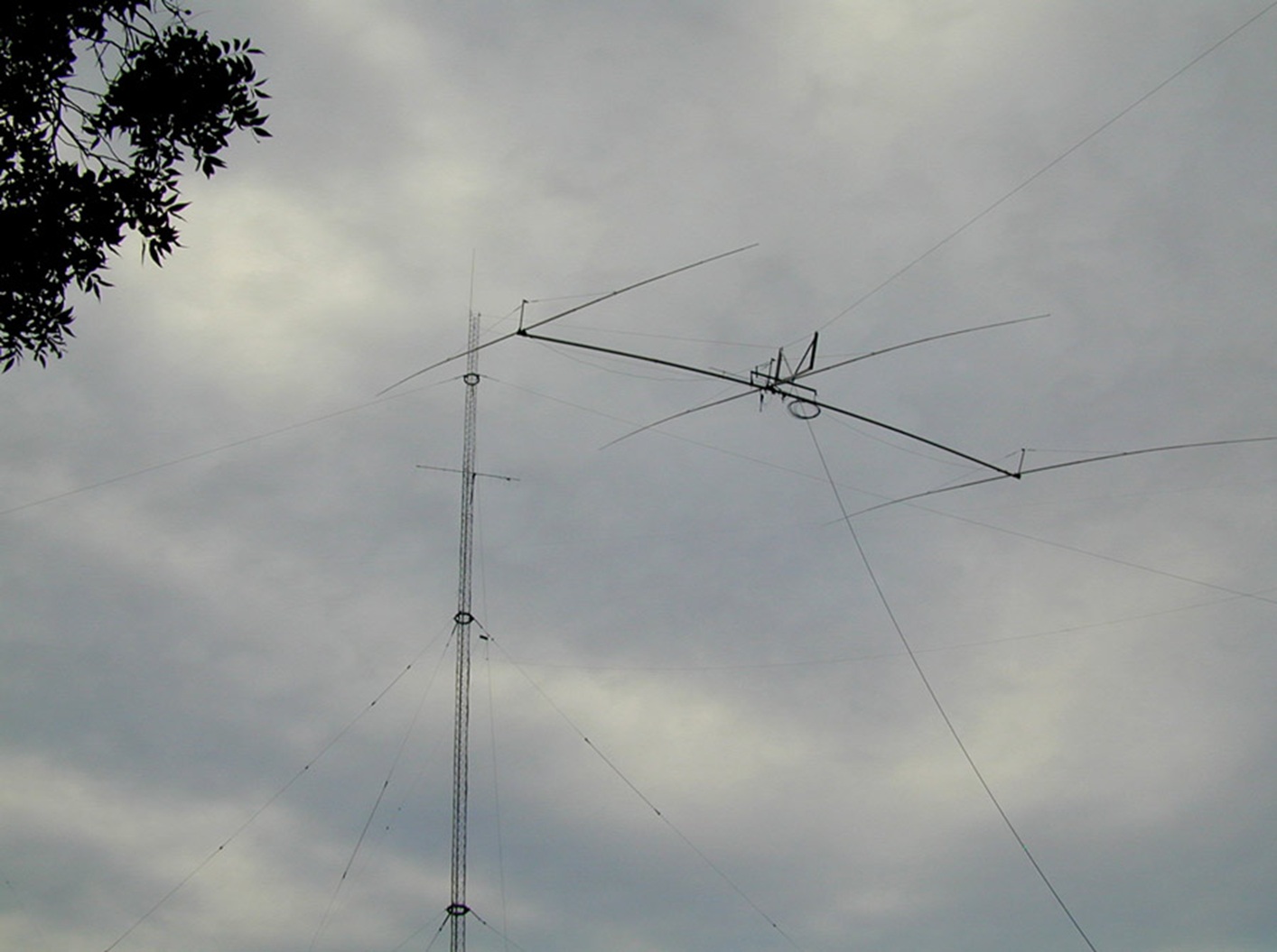
The 4-ele OWA 40-meter Yagi on a 30-meter rotatable mast (14.Apr.2025)
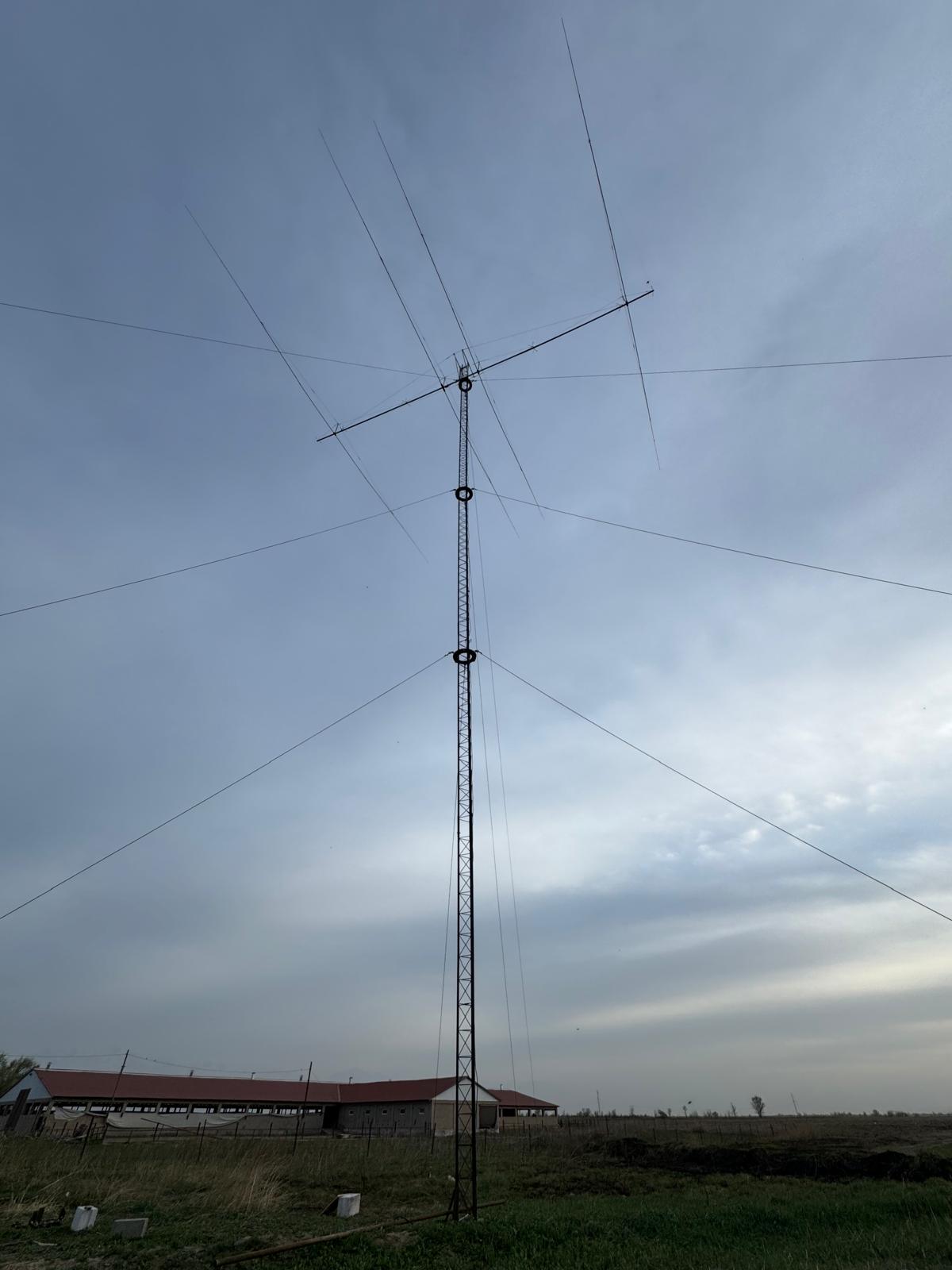
On the day of tower erection, I didn’t risk installing the two upper 6-meter sections and the upper orbital bearing, as there were multiple uncertainties with the design. I wanted to make the tower and the antenna prove themselves first in times of winds, etc. Thus, for the time being, the 42-meter tower is a 30-meter tower 🙂
Stay tuned.
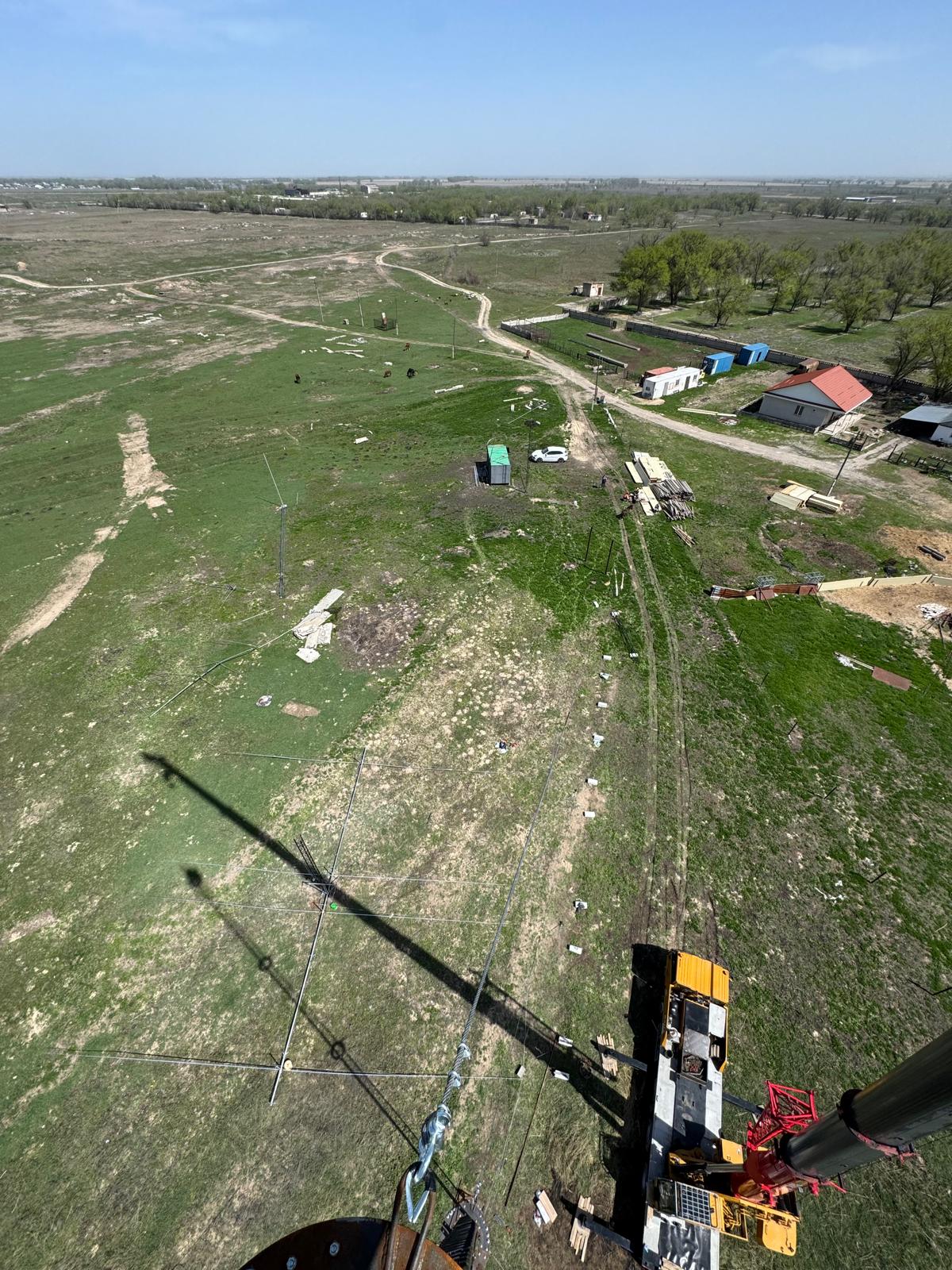
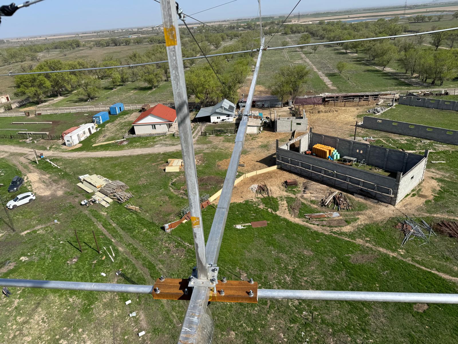
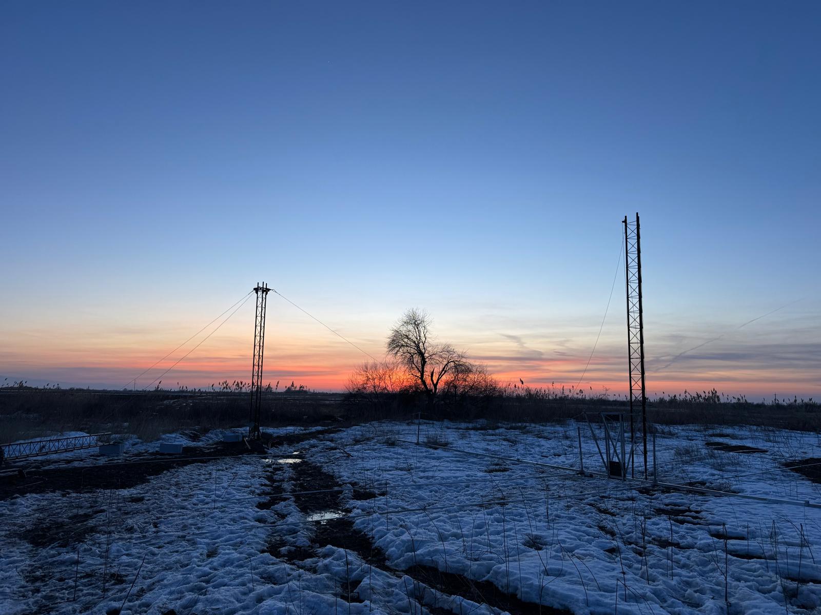
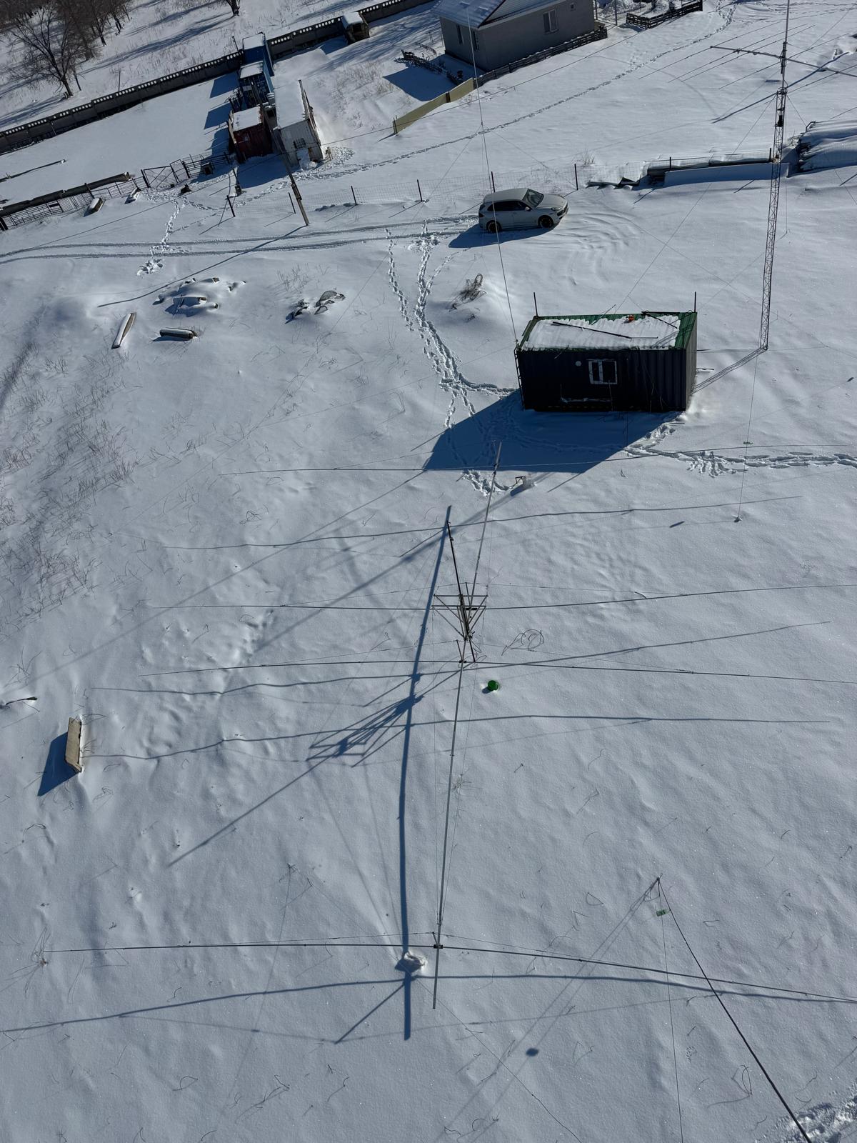
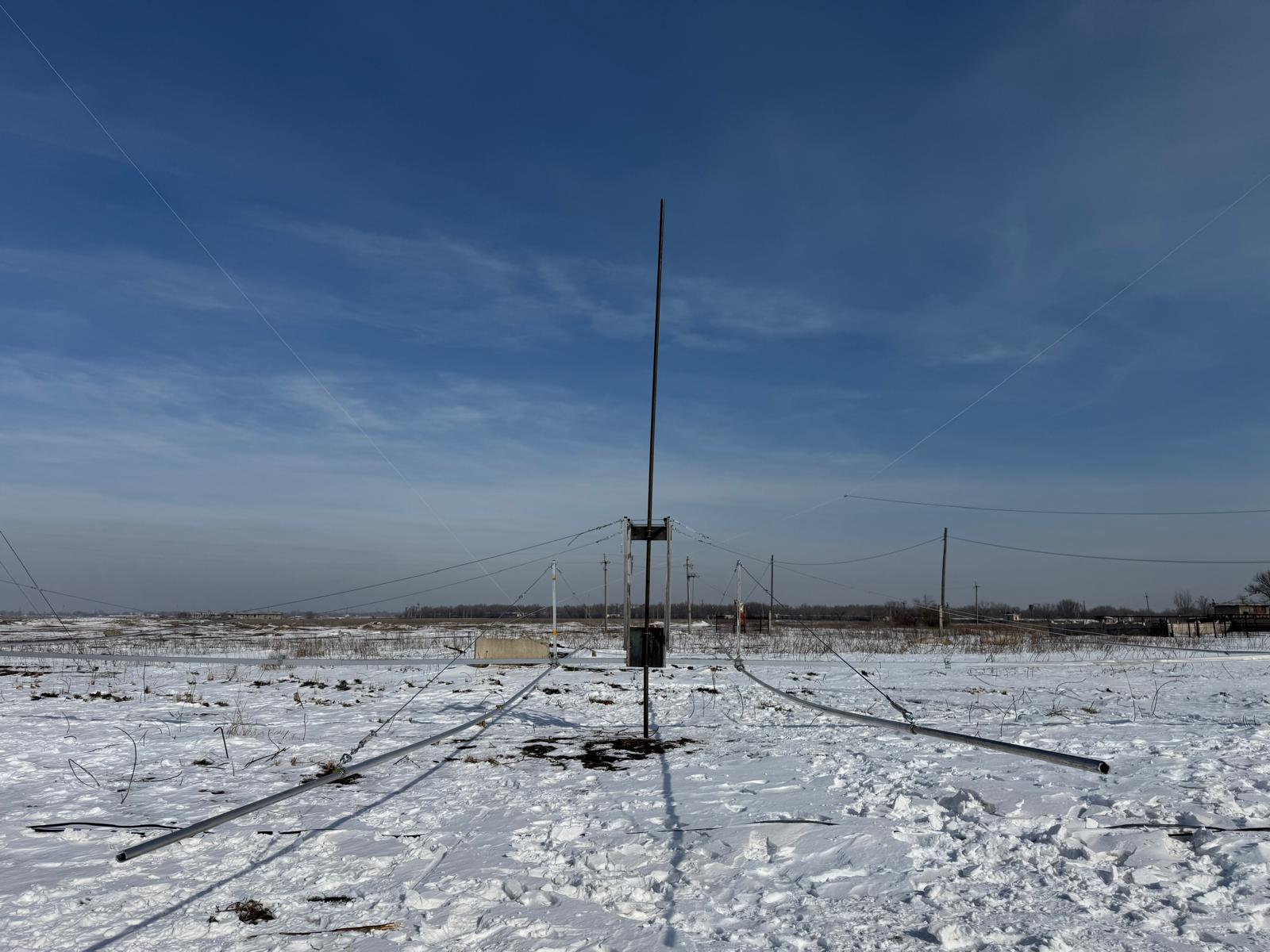
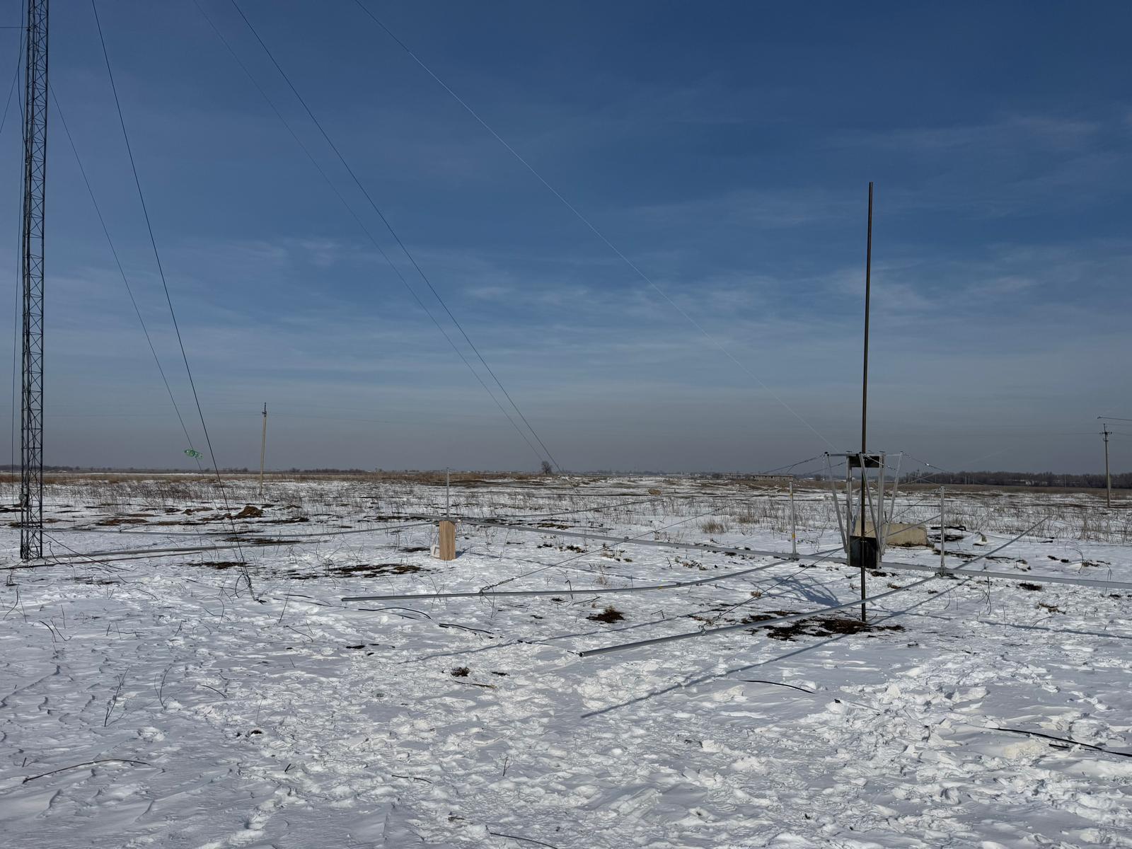
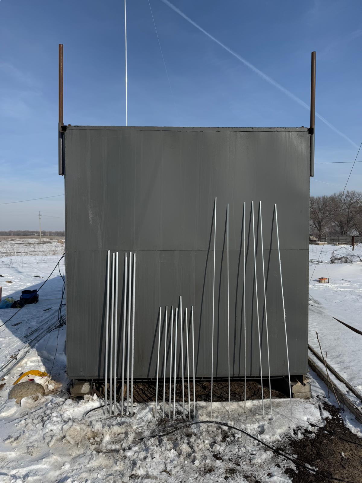
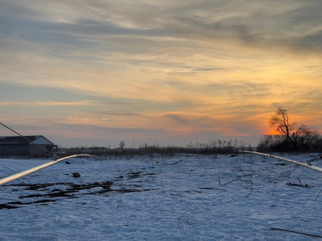
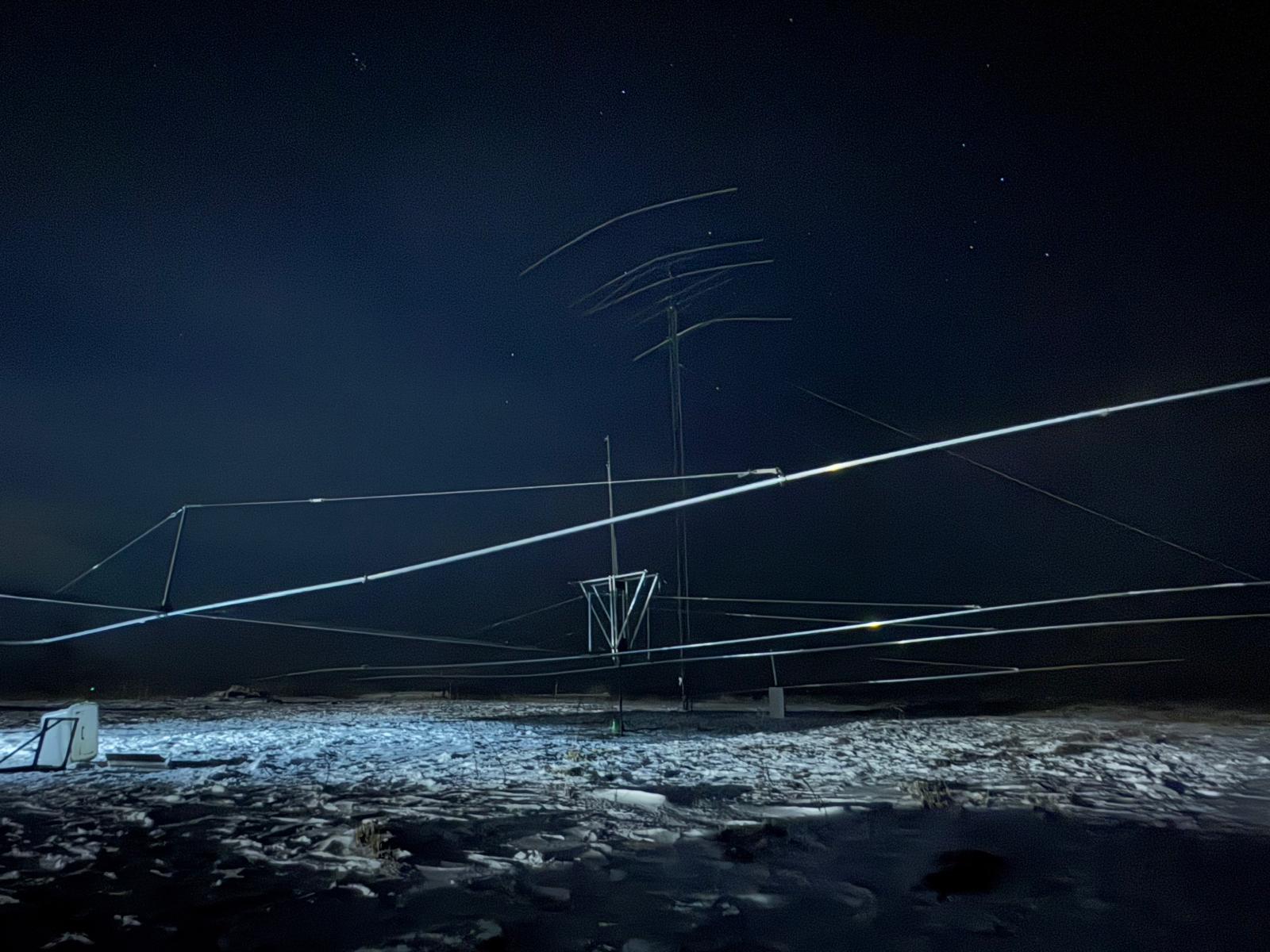
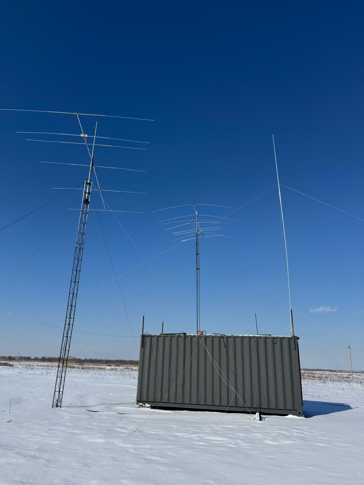
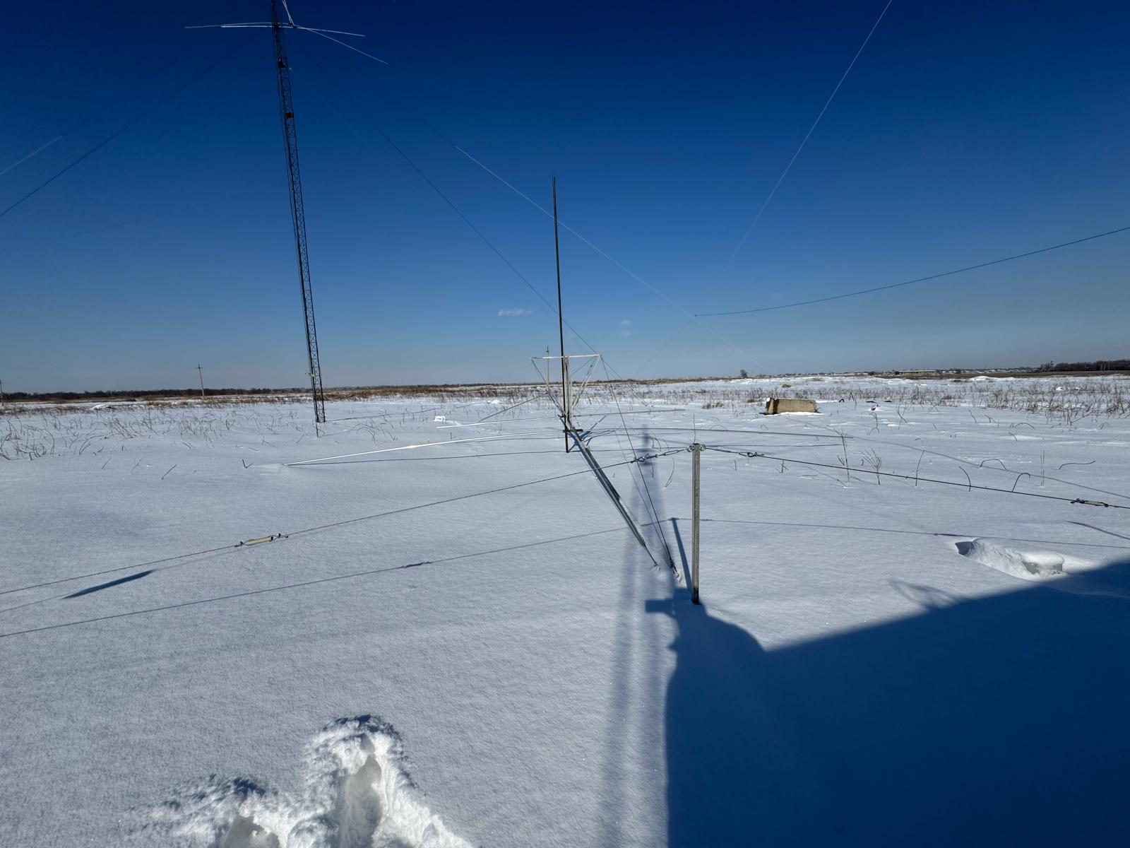
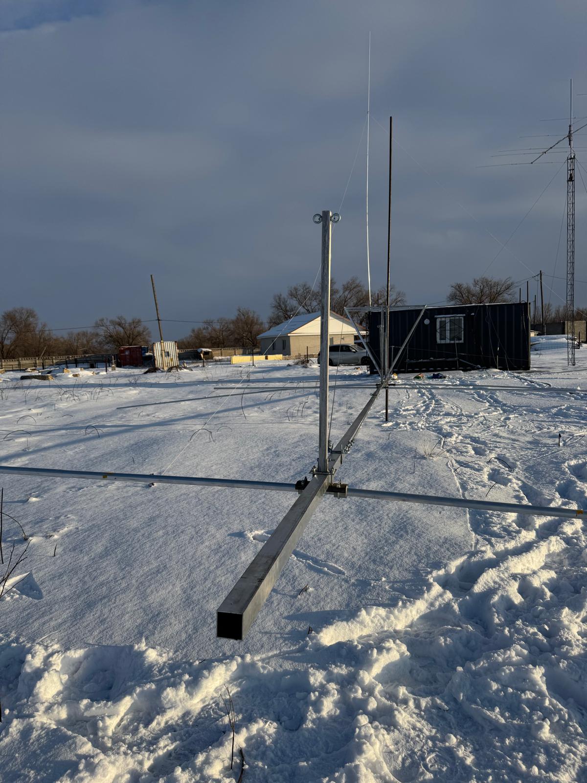
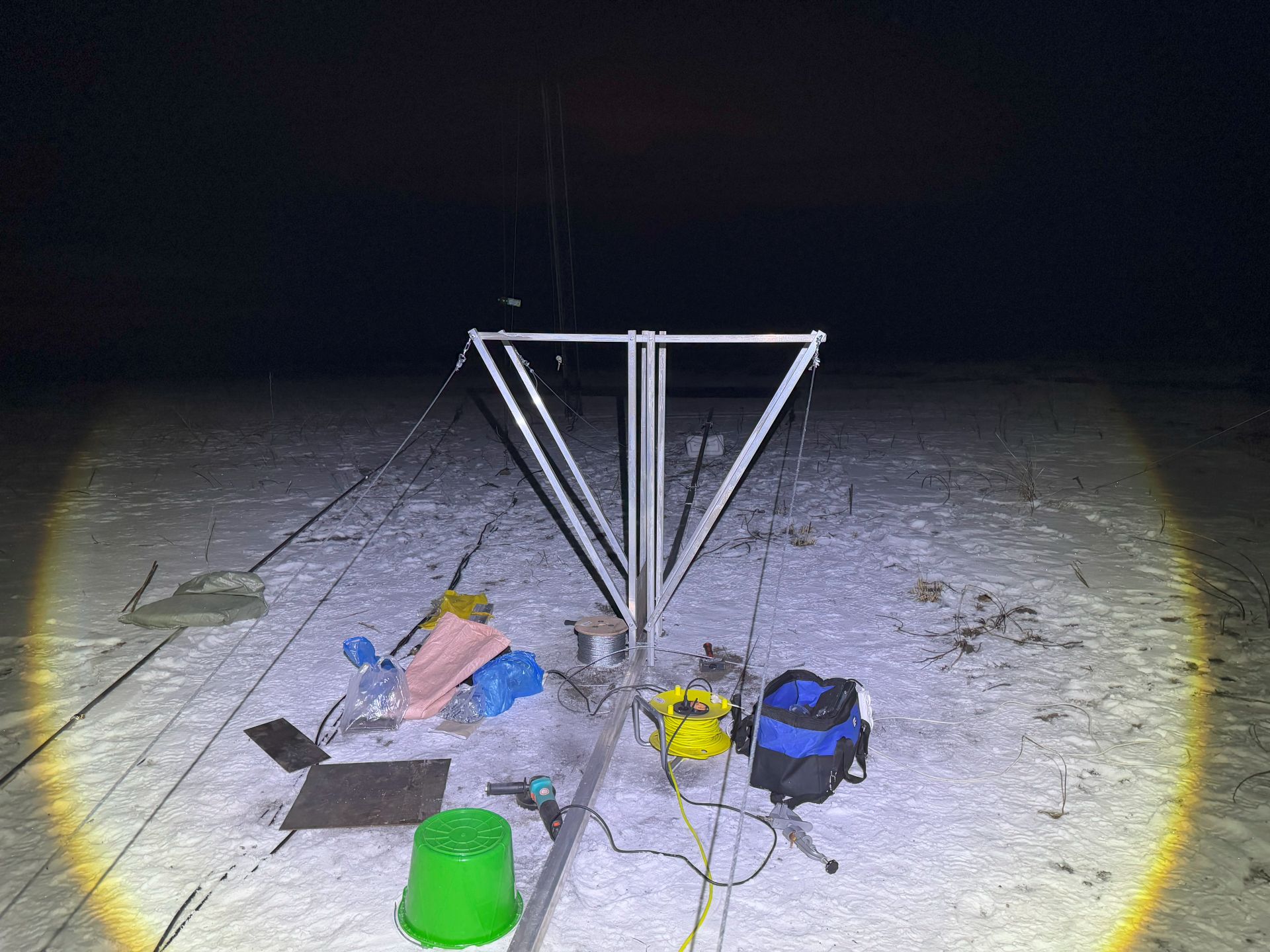
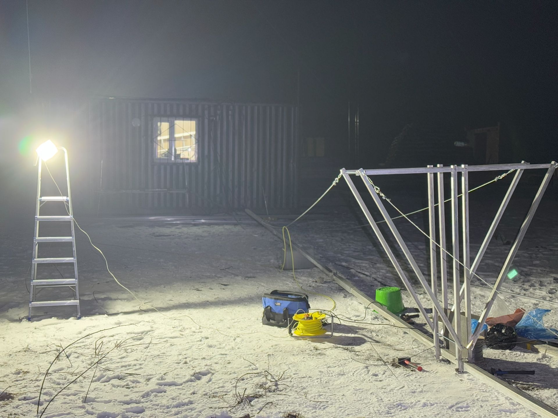
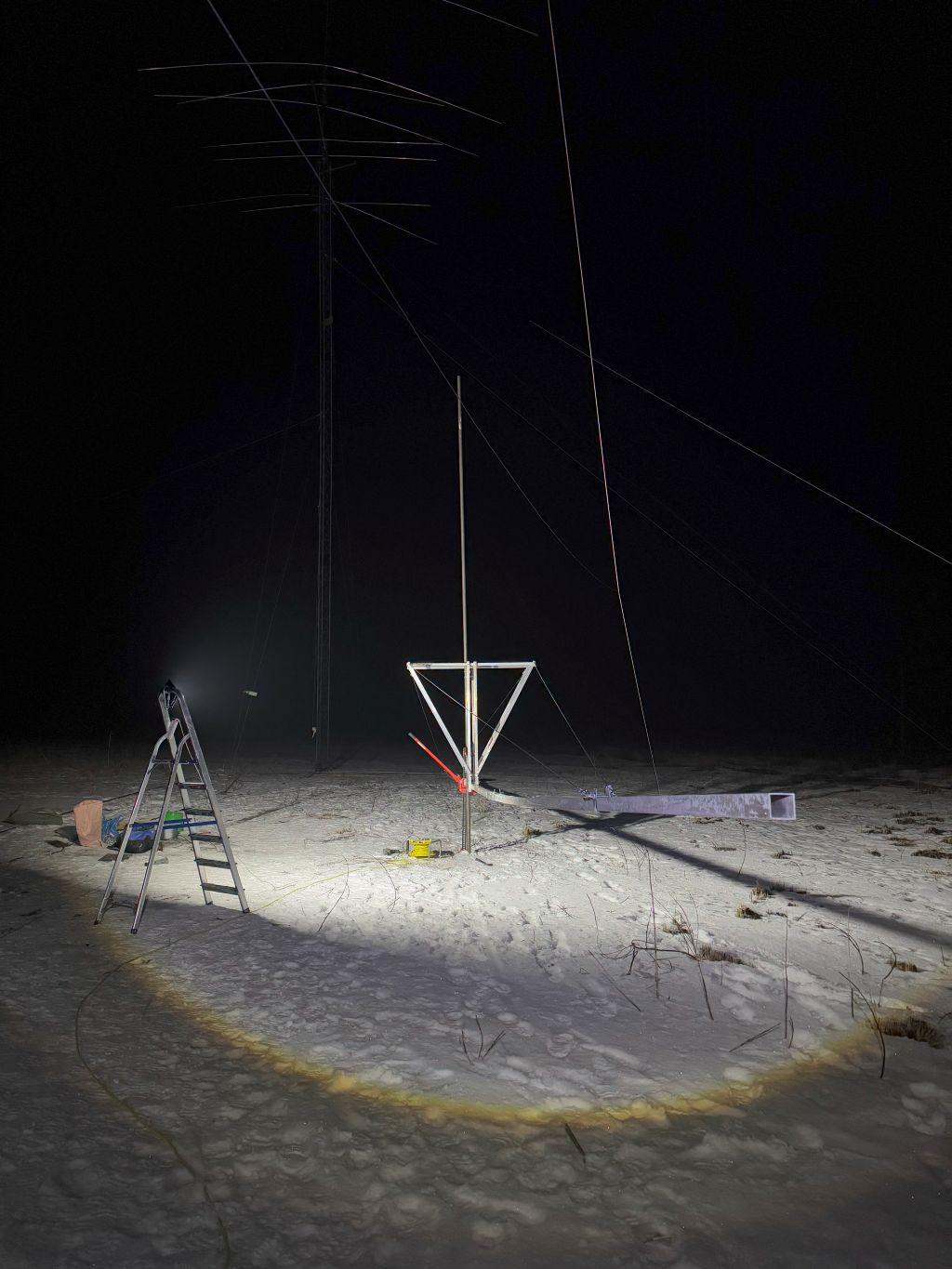
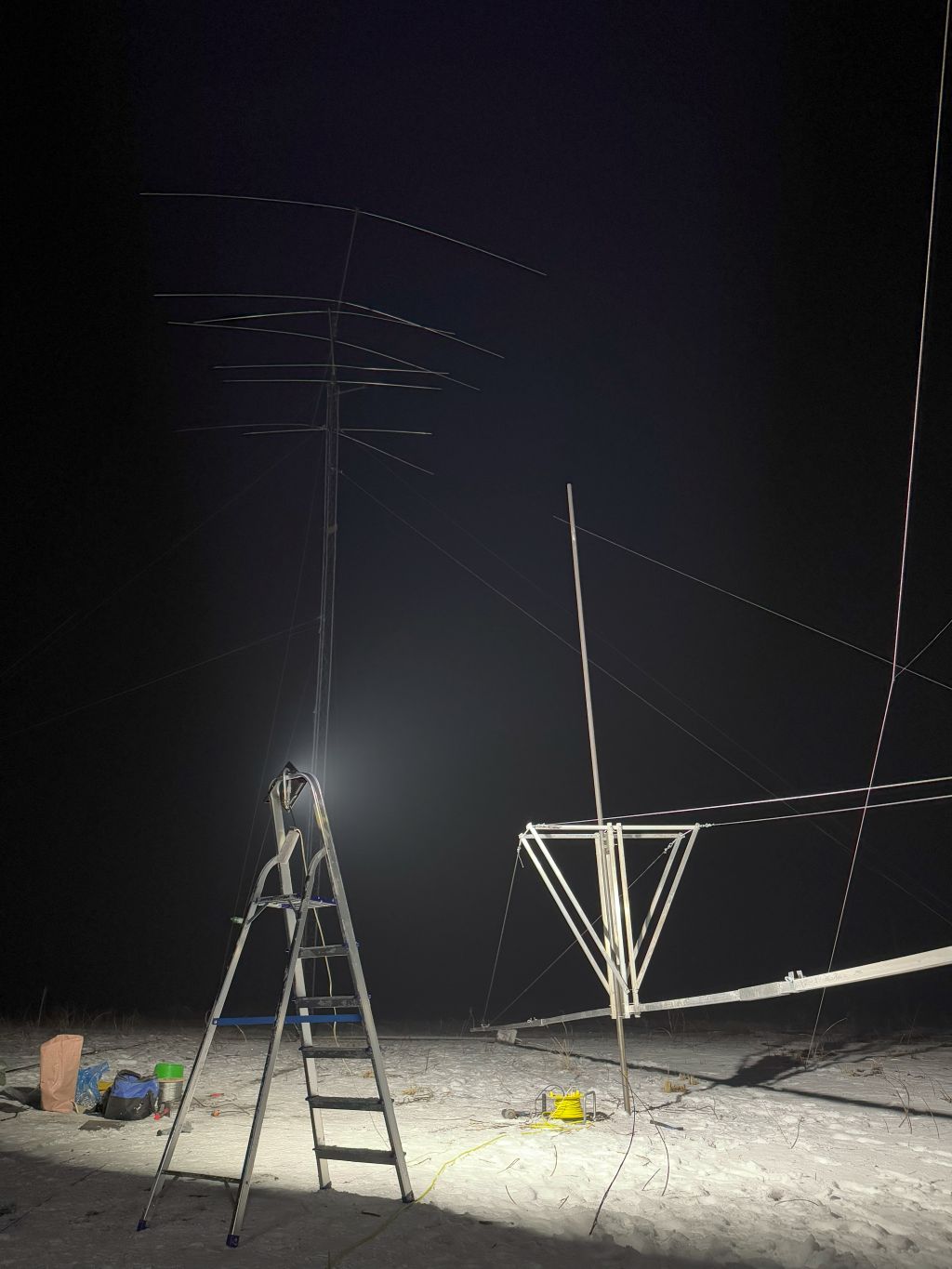
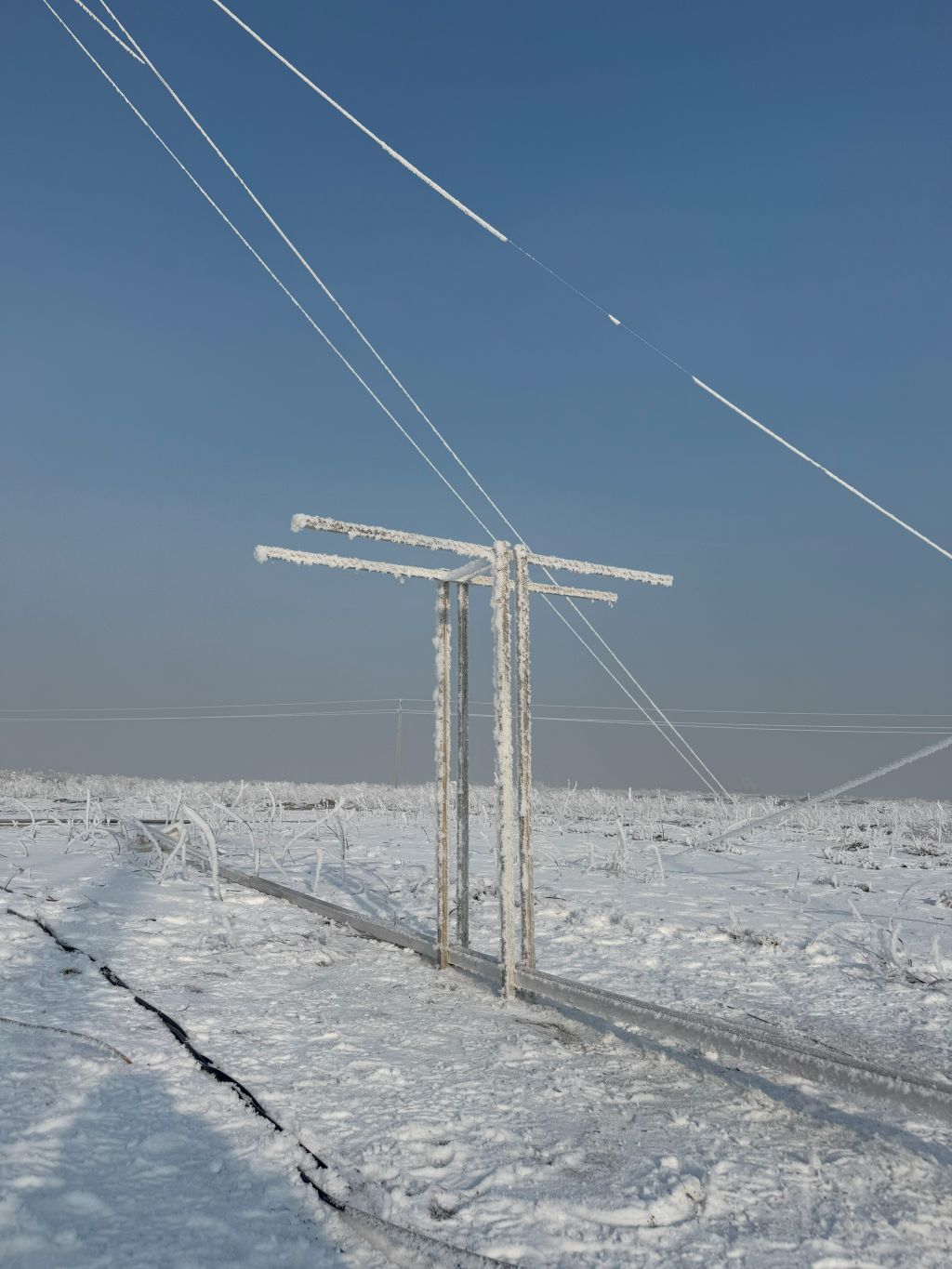
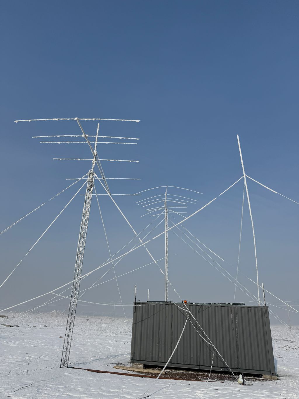
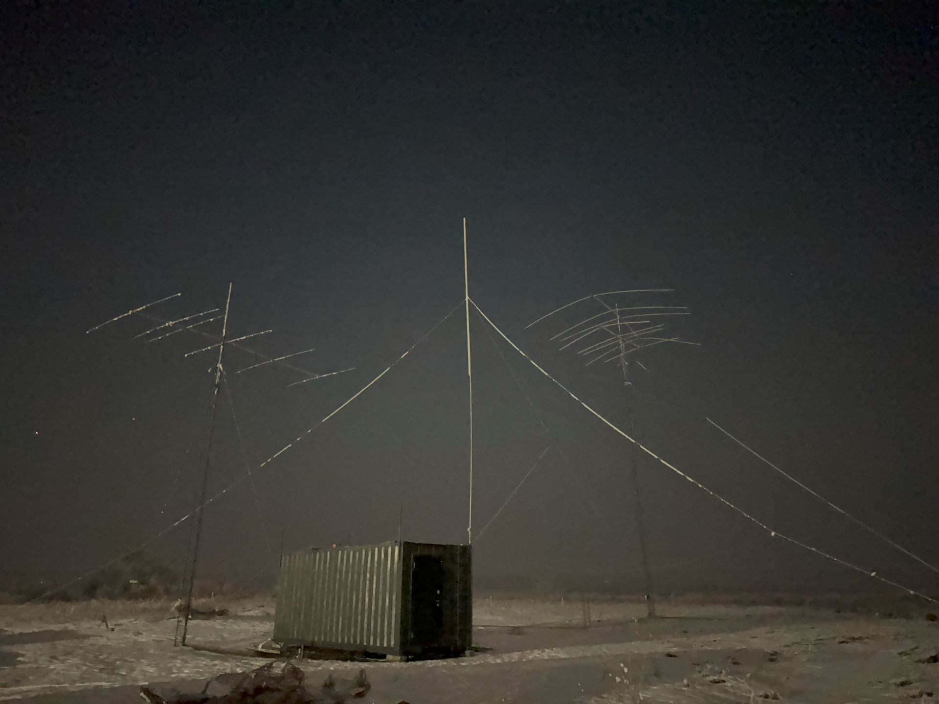
The remote QTH view before the star is born ...

P.S. The 18-meter tower (on the back) with a 4-ele OWA Yagi for the 20-meter band and a 4-ele OWA Yagi for the 15-meter band fell to the ground during a basic antenna check-up smashing the antennas entirelly in the beginning of April 2025 – just a few days before the 40-meter Yagi to be installed on a new tower. RIP 🙂
But several weeks later, I and my brother (ex-UA3LFV) installed a new 20-meter 4-ele OWA Yagi – even a better and stronger version of the antenna.
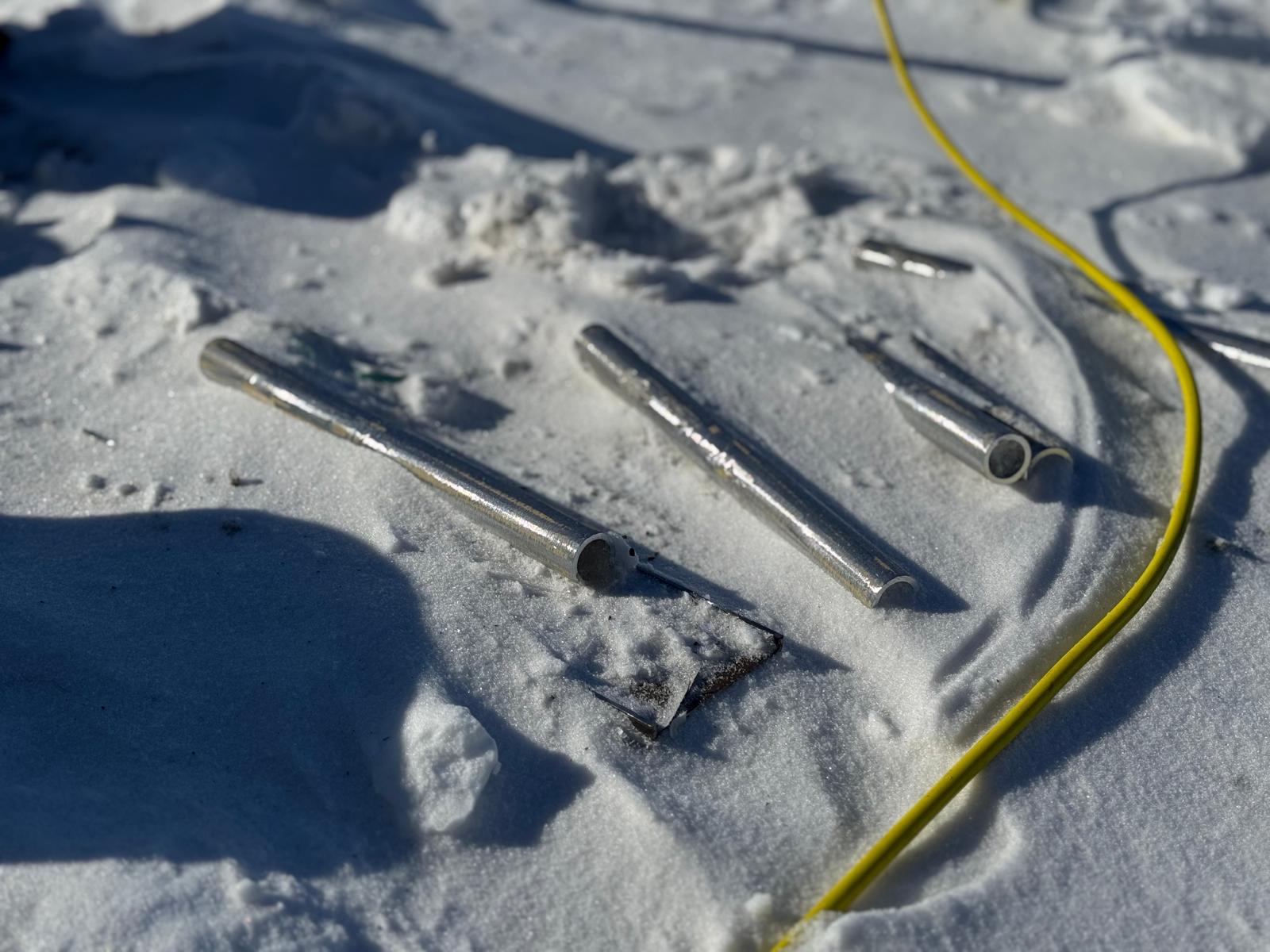
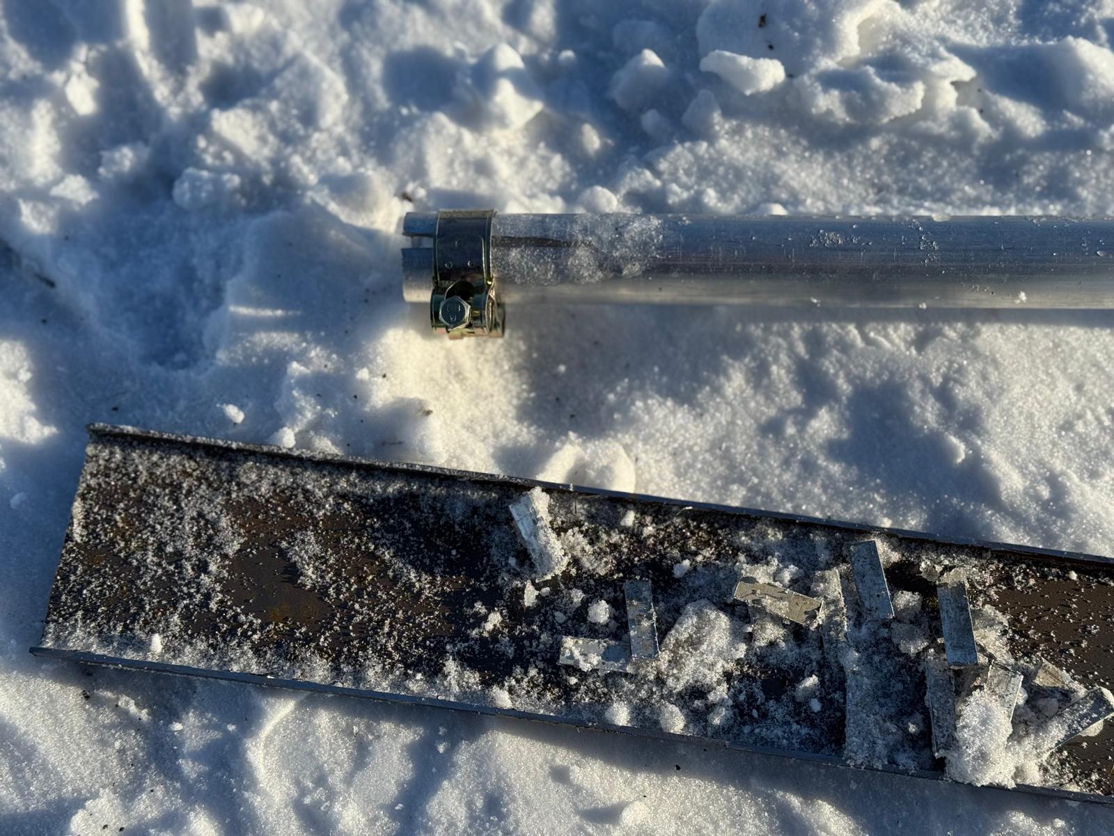
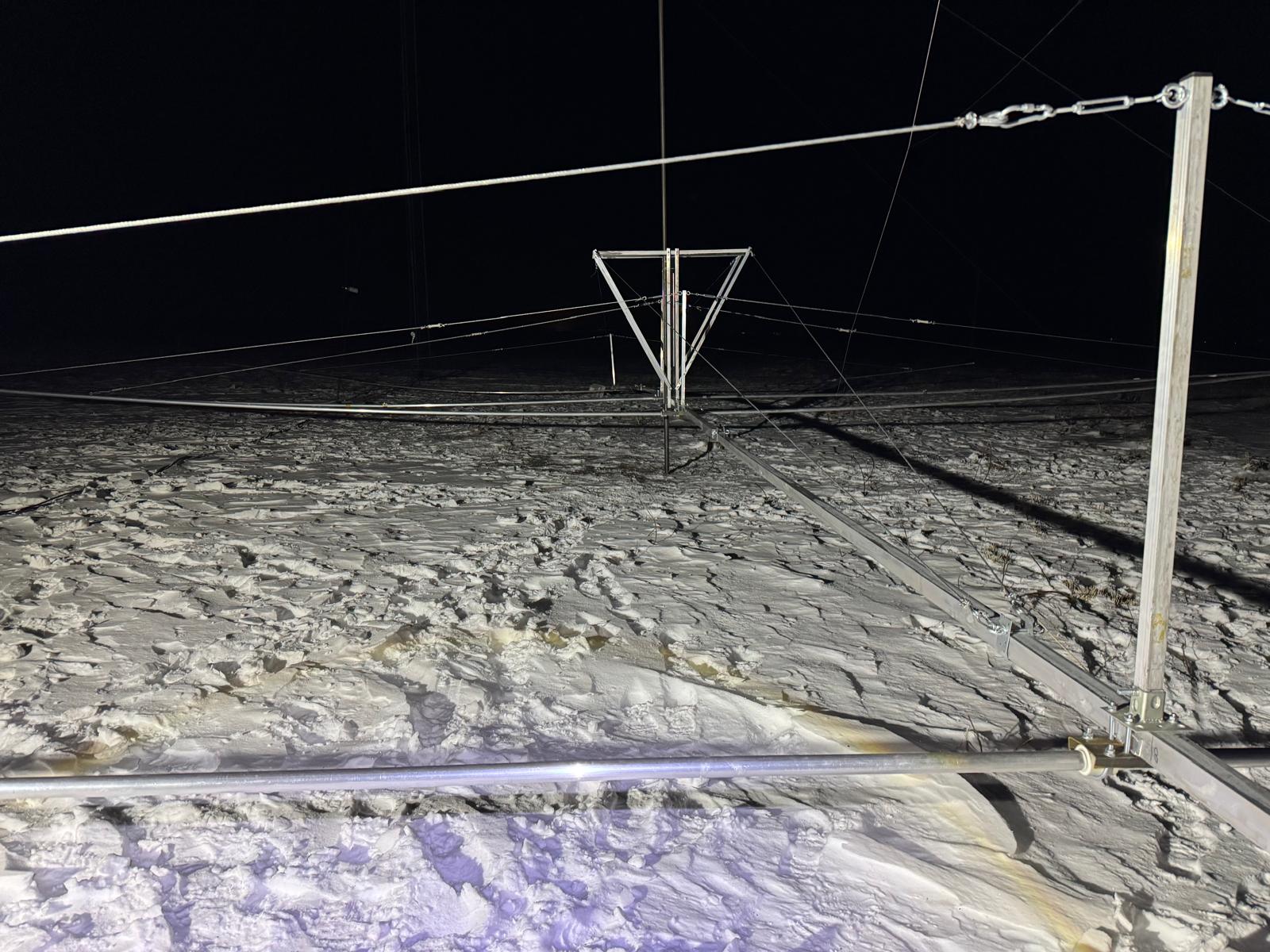
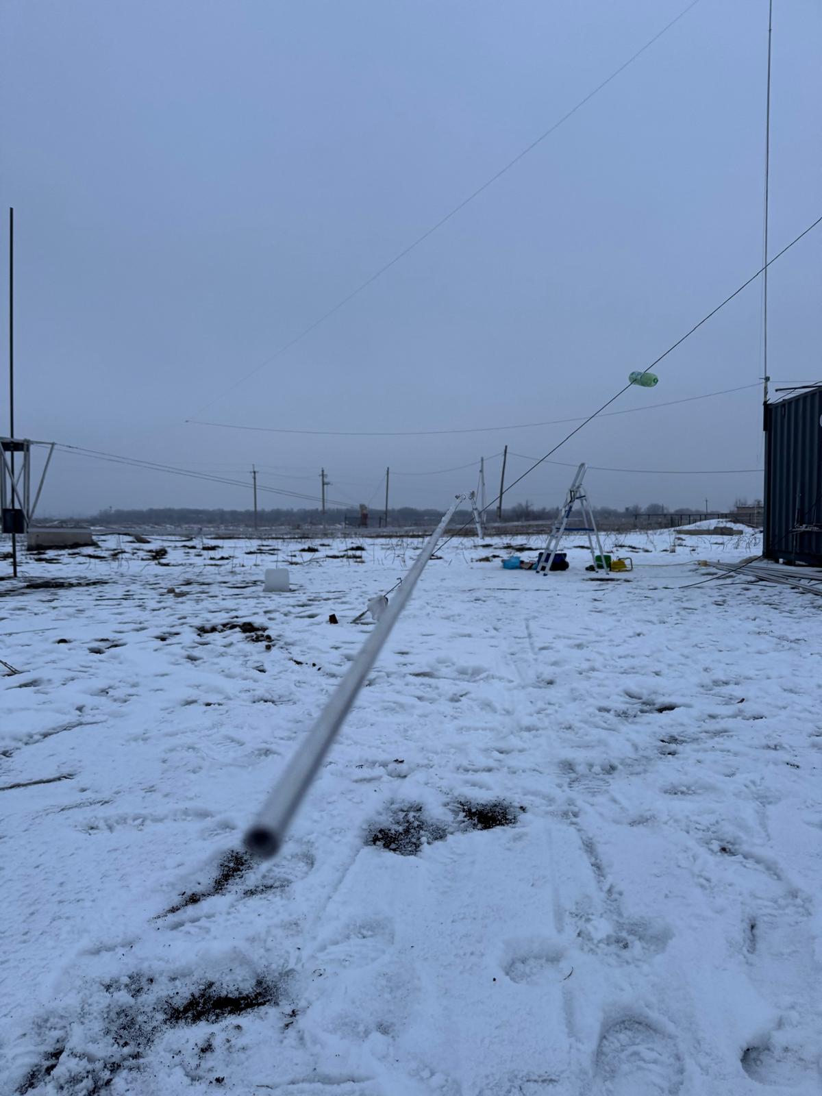
2025.May.23 - Yagi is lost in action
It was a slow-moving and hot day. Together with my wife, we came to the QTH to do nothing – check here and there. After a few hours, we departed towards home, a bit more than an hour’s drive to the center of Almaty.
However, a few minutes into the road, the wind gusts turned out to be quite nasty, and I started to suspect something was wrong. A few minutes later, I received messages and photos from the landlord. The Yagi has gone. Sad.
It survived a few milder storm SMS announcements (20-25 m/s), but didn’t survive this one. One month and 10 days.

Conclusions:
- A 50x50x2 mm profile is clearly not enough for an 18-meter boom. 80-100 mm seems to be the better option. Either I need to order something special or build a 50+50 mm – a double horizontal boom. I thought to make it vertical, but the boom guys keep the boom strong enough to withstand its own weight and the weight of the antenna. However, against the wind, it must be a stronger structure horizontally
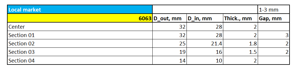
- Profiles of elements starting 32/25/19/14/10 seem to be good enough
- One layer of guys supporting elements is also enough
- Kevlar lines keeping elements in place isn’t a bad idea
- Broken boom/Yagi is bad. But a survived tower is much better
Well. I nearly thought that everything is settled and the Yagi will continue to work. But the weather showed the fallacies in the design.
Nevertheless, I enjoyed the 40-meter with such a nice antenna, had a few DXs, including Panama, and now have a much better understanding of the band.
The nearest time plans include:
- Downing the 40-meter Yagi
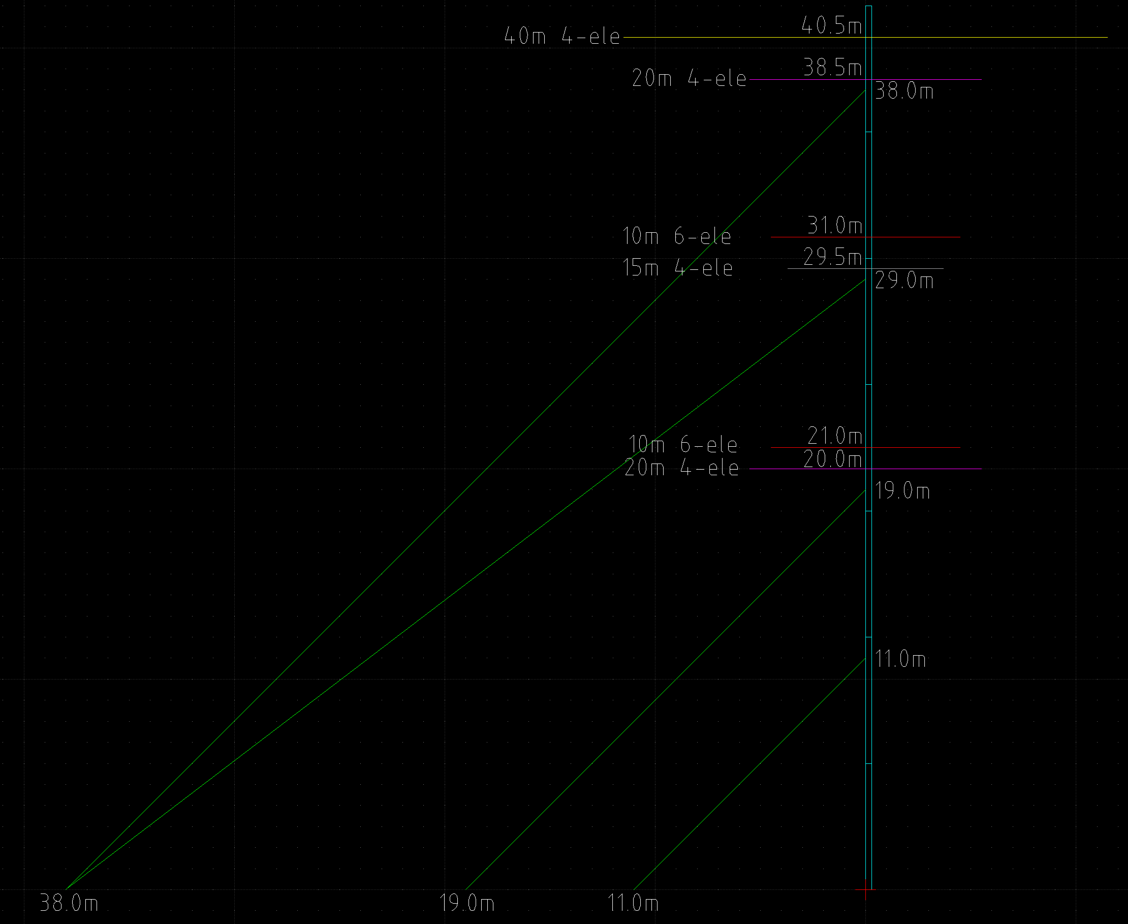
- Putting two more sections of the tower and an additional bearing, thus increasing the height of the tower to the originally planned 42 meters, because 30 meters is good, but all fun starts above that height for DXing, and all the options for stacking as well
- Replacing the 40-meter Yagi with a 20-meter Yagi and installing 10-meter 6-ele OWA Yagi and a 15-meter OWA Yagi on the tower
- Particular interest is in comparing the performance of a 10-meter Yagi at 10 meters height and 30 meters height, as well as a 20-meter Yagi on 19 meters and 40 meters
2025.May.14 - general updated
- The mast has not fallen yet, which is a great thing in its own right, because it wasn’t obvious when designed or installed. Lucky we are 🙂
During one of the wind gusts, a Kevlar line supporting the reflector entangled with the reflector and bent it. Results:
- Slightly bent reflector
- No support from one of the directions
- And slightly better SWR 🙂
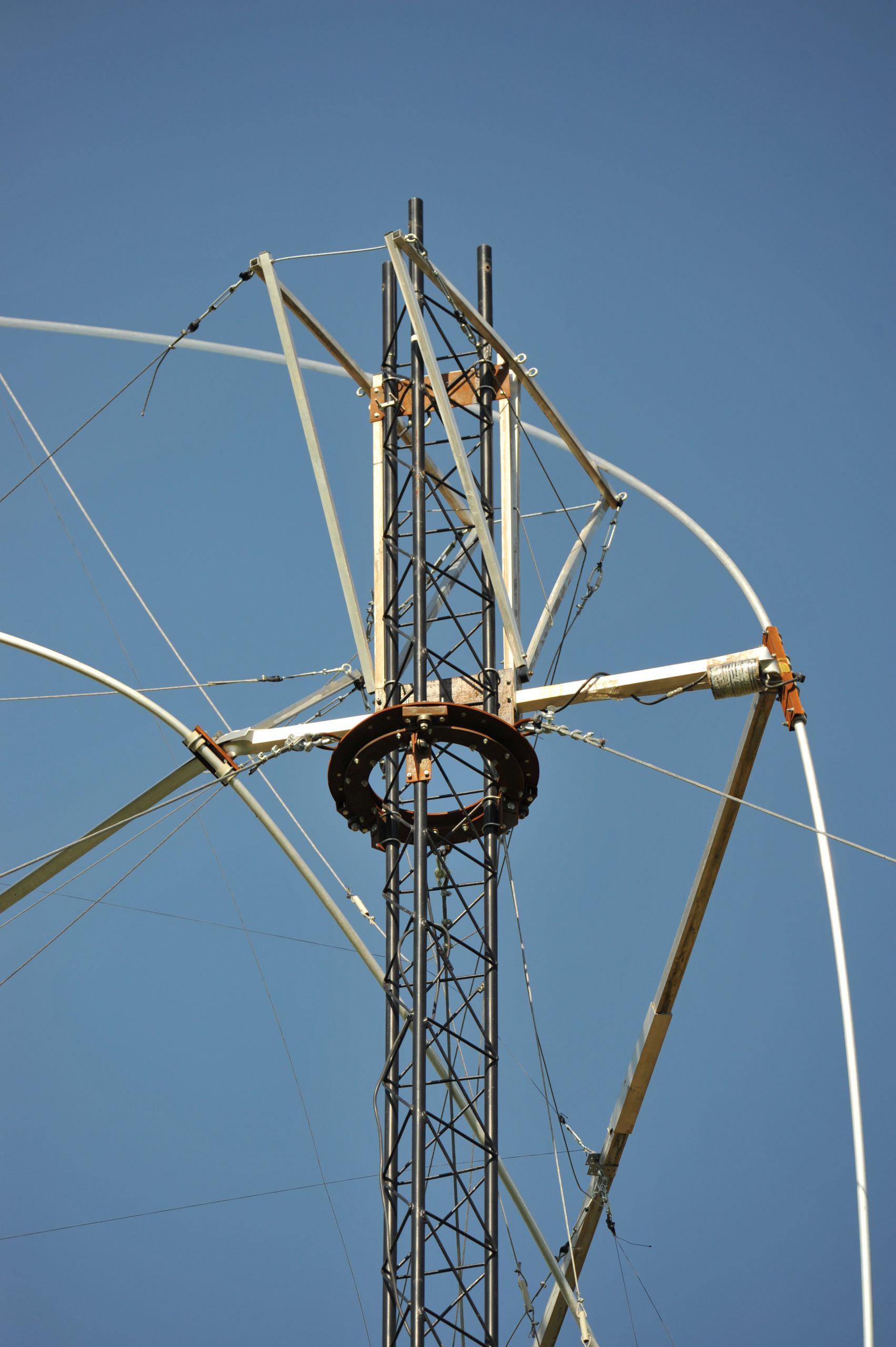
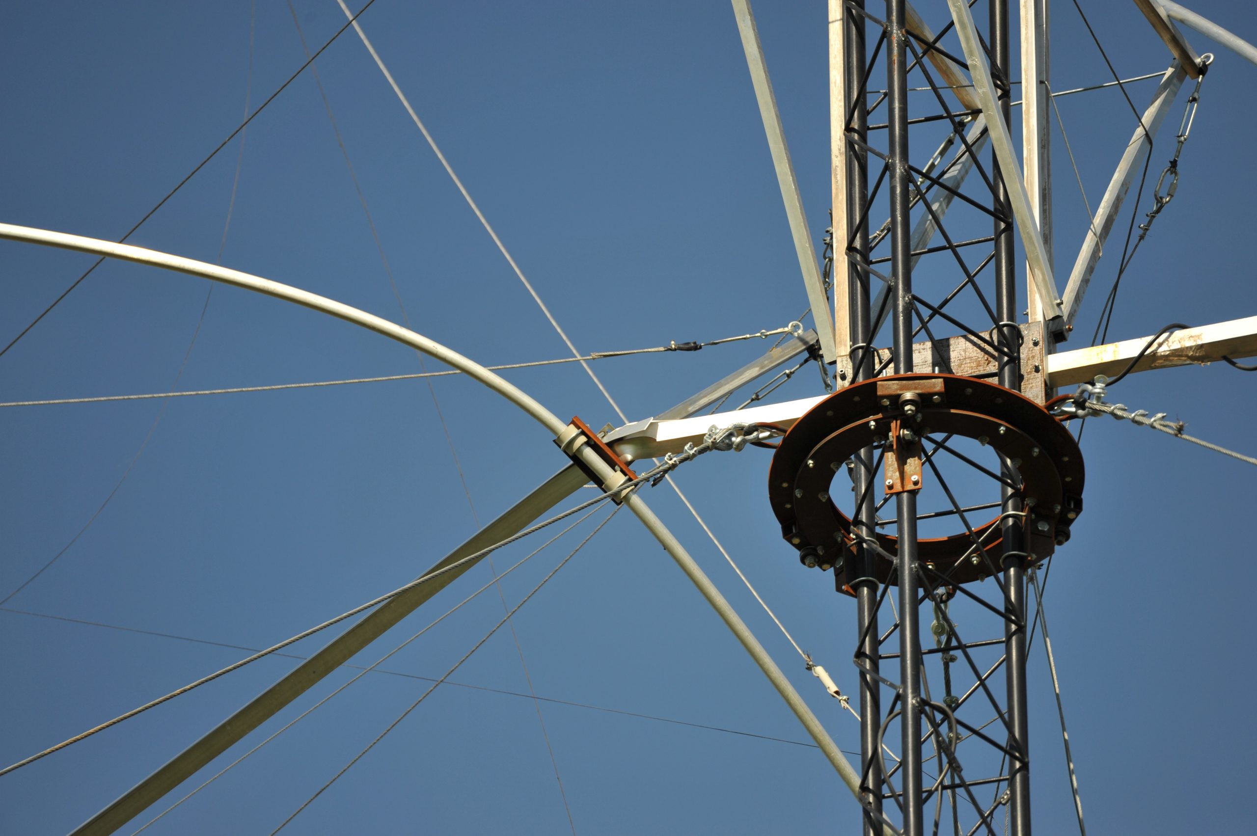
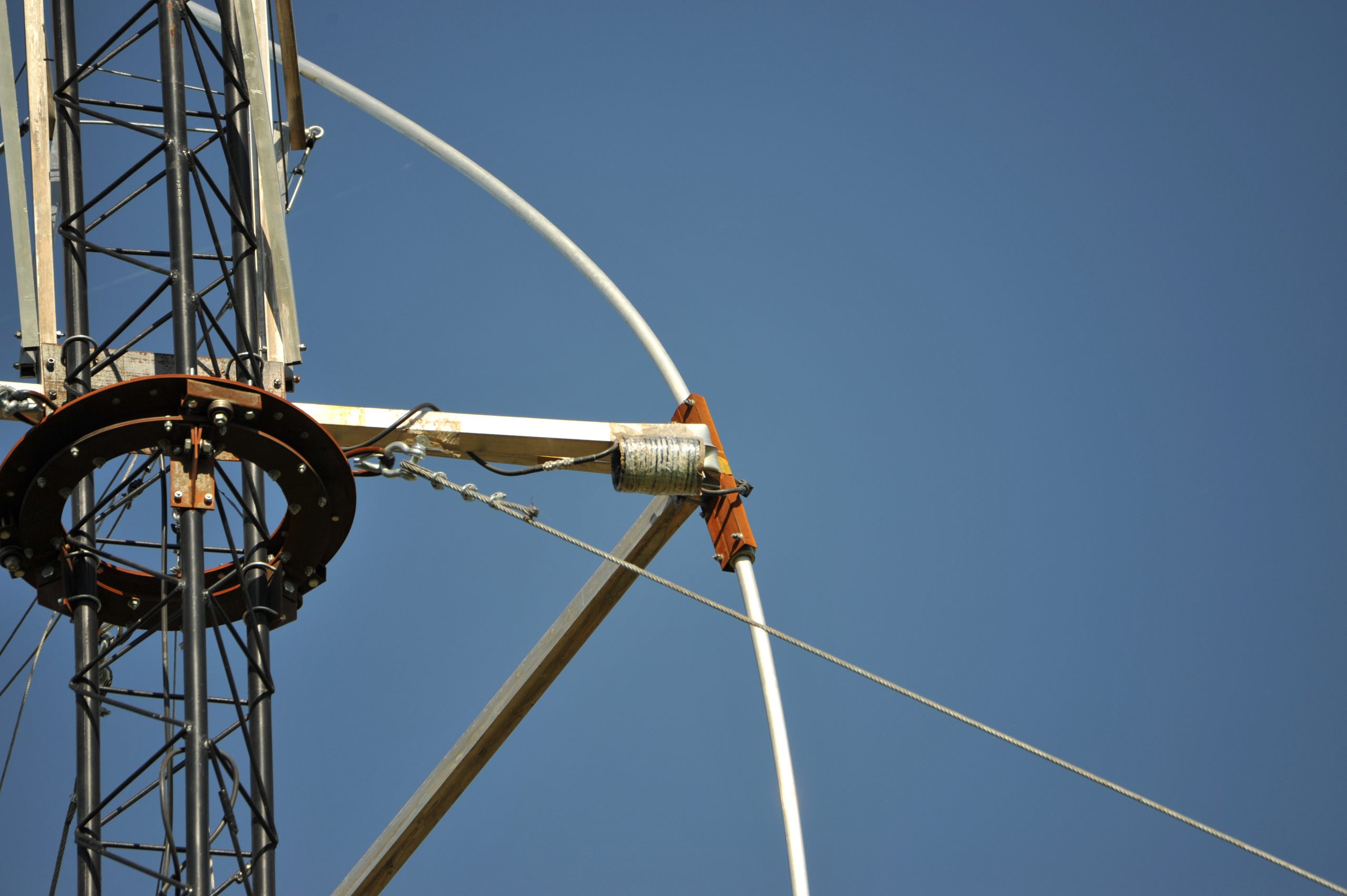
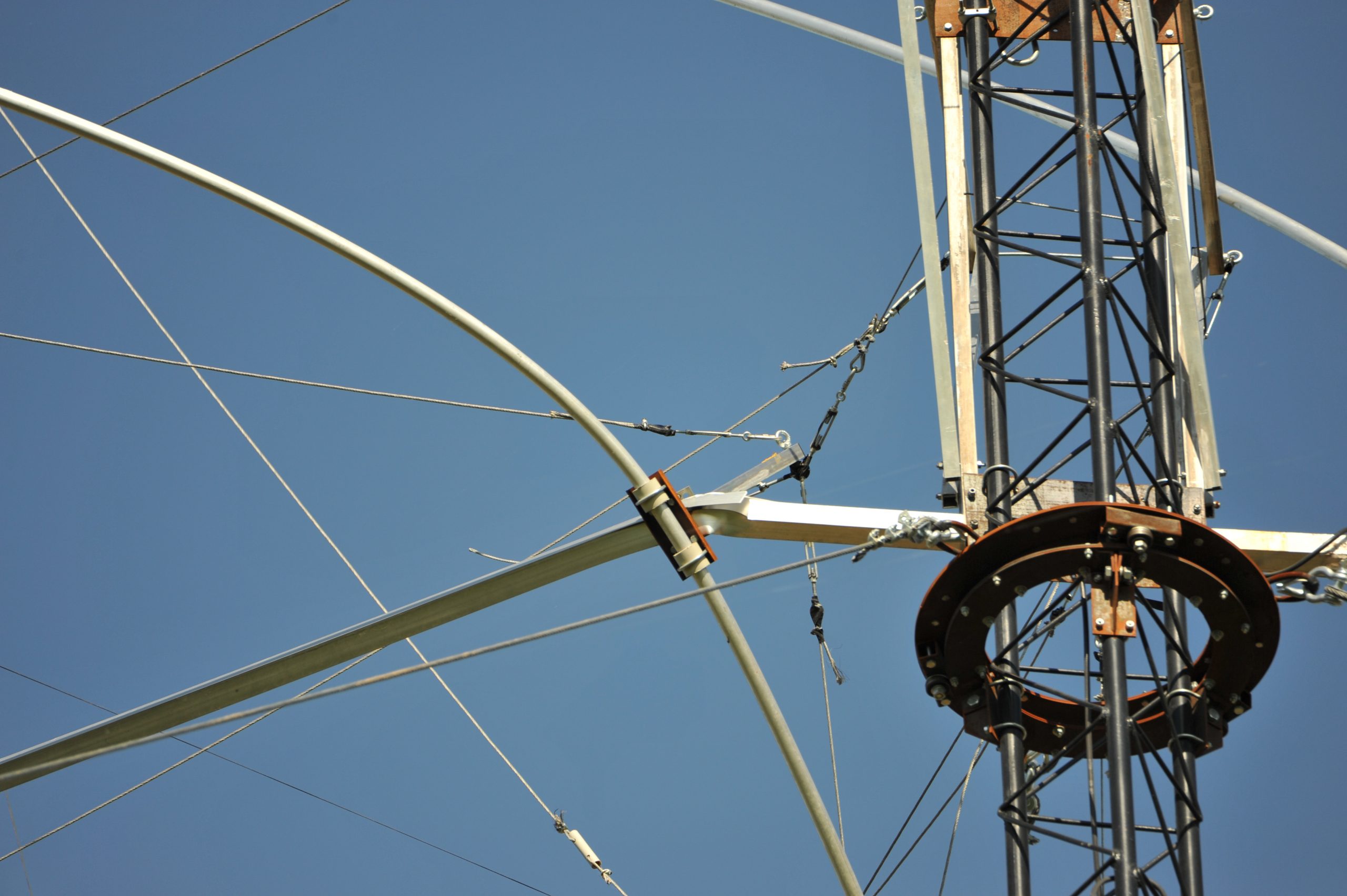
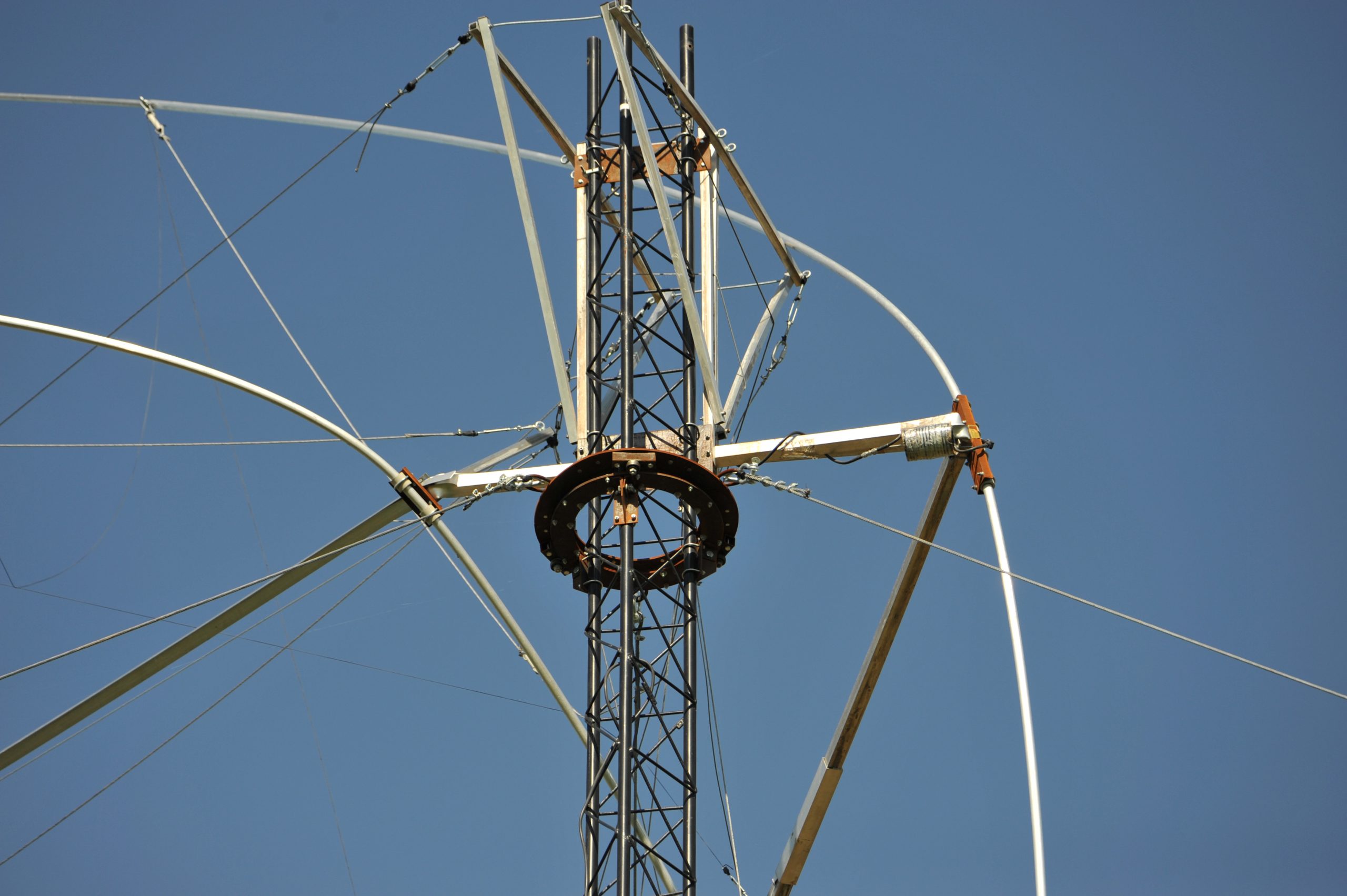
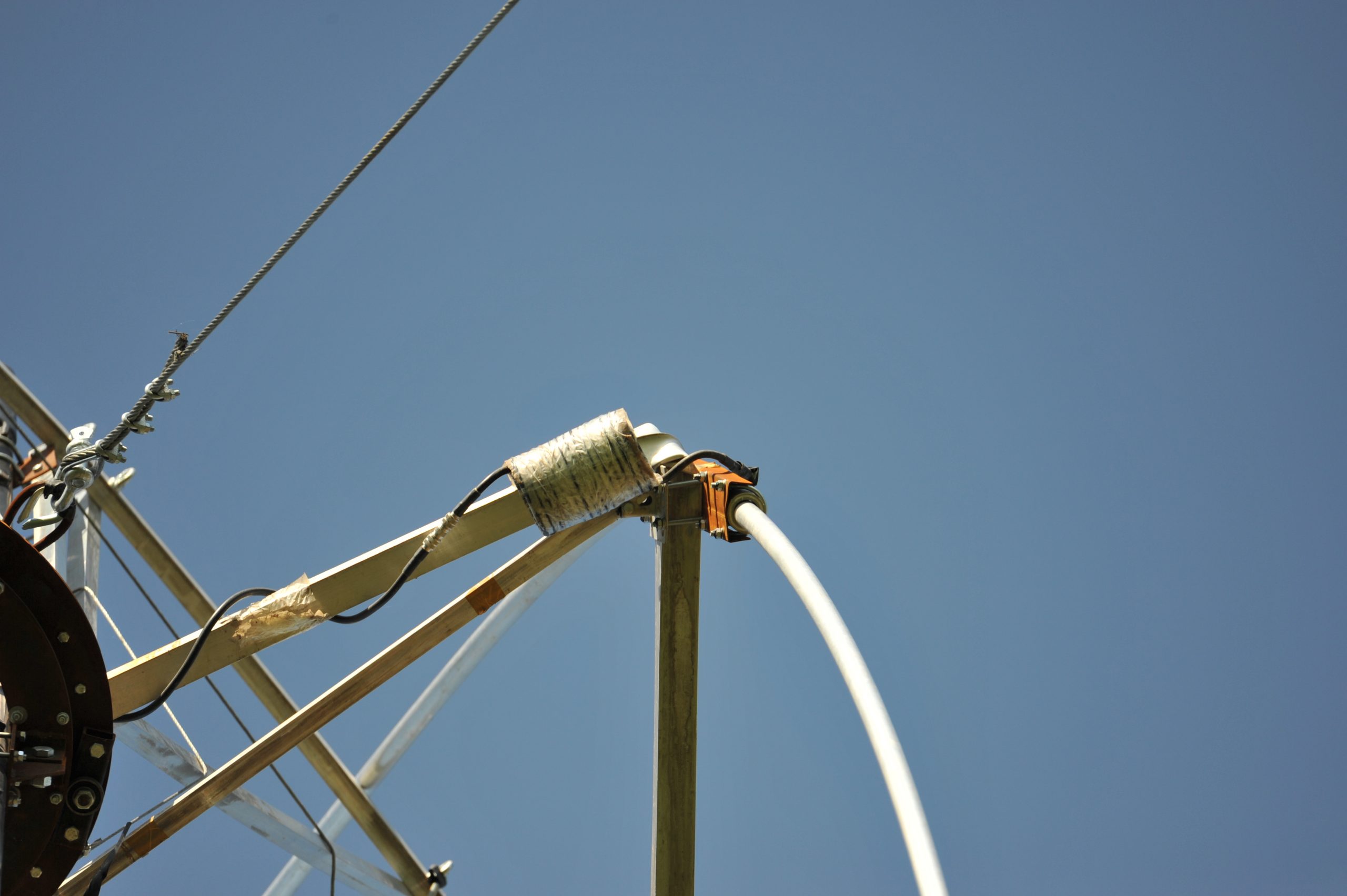
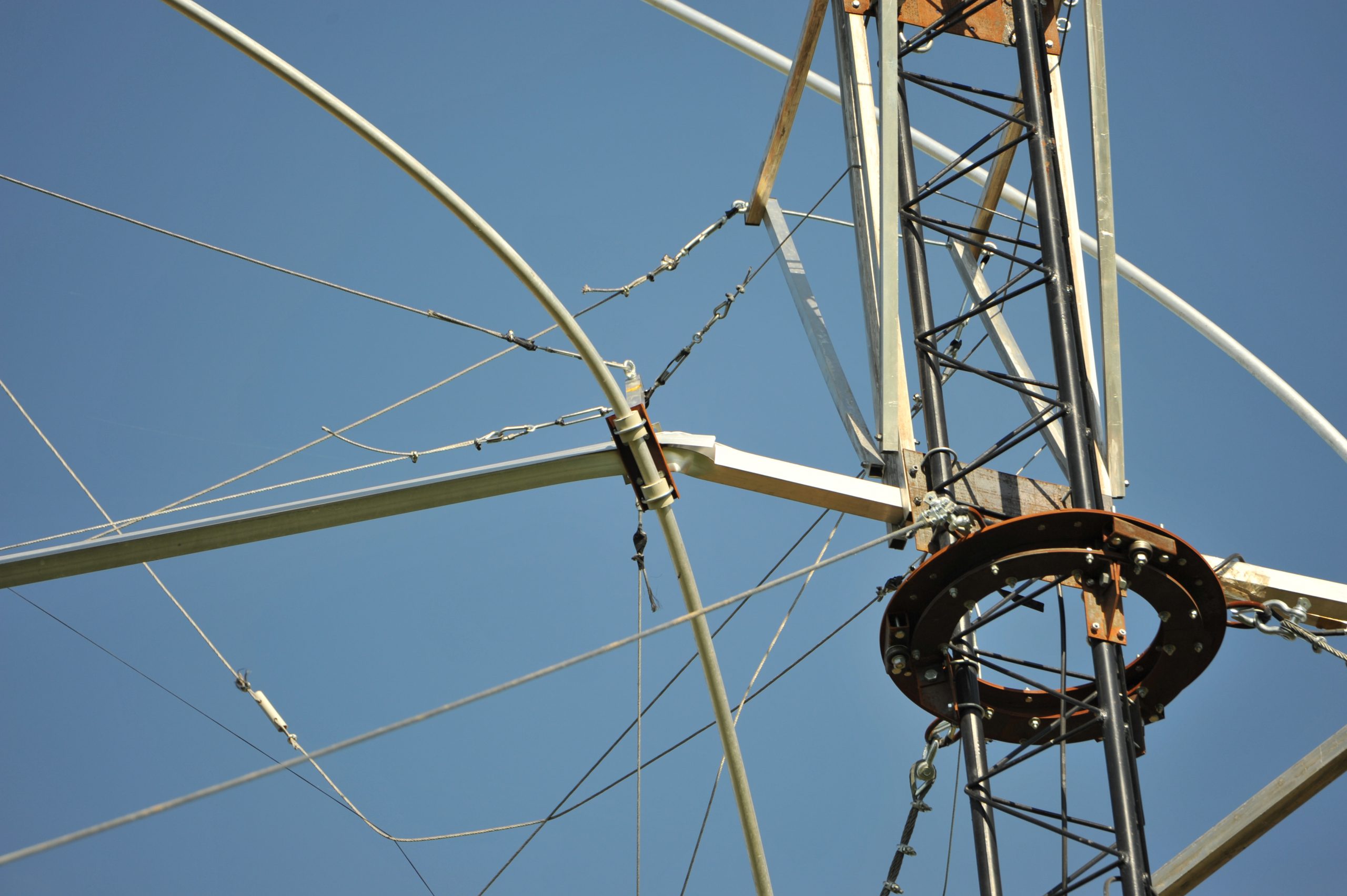
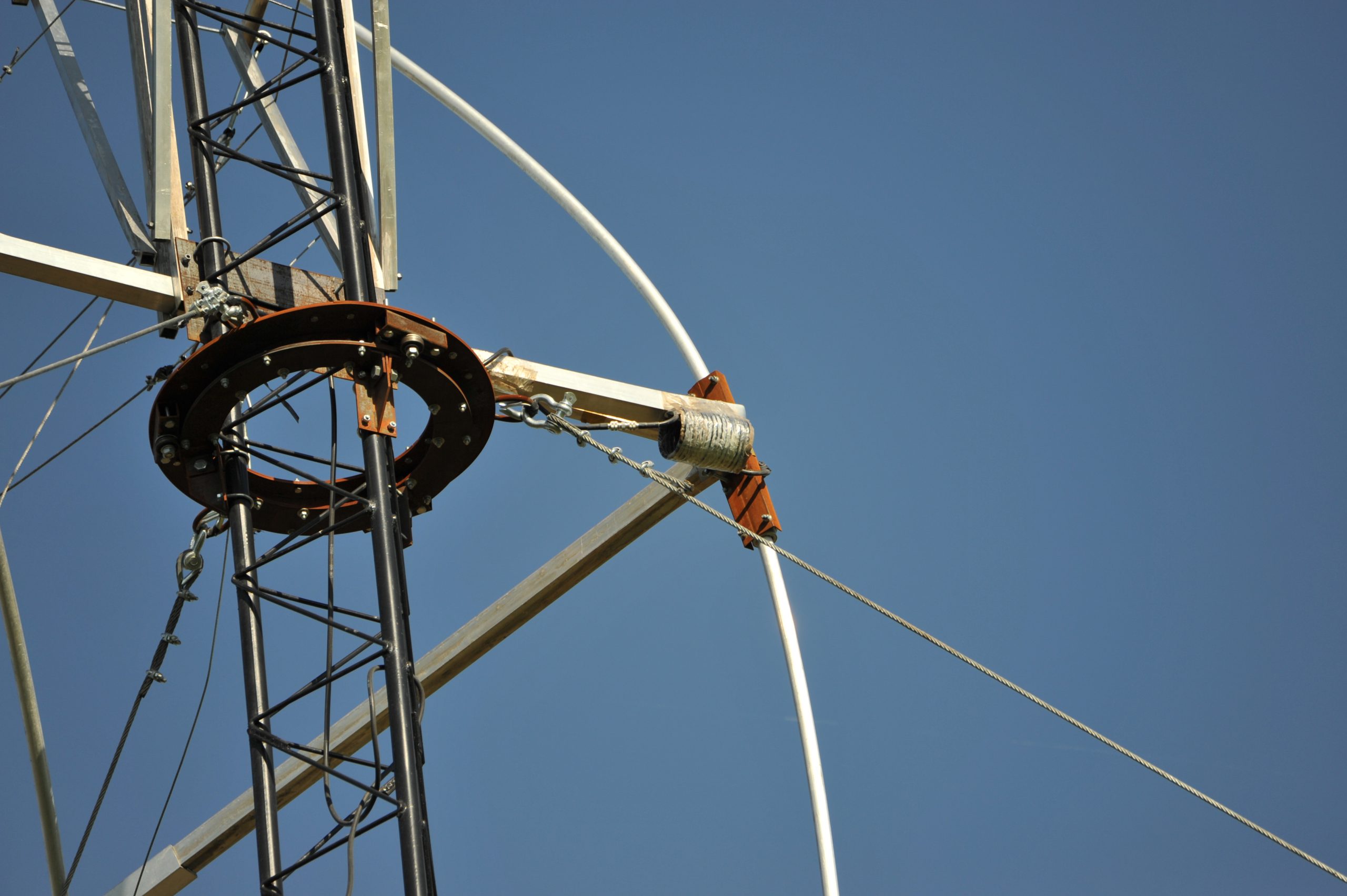
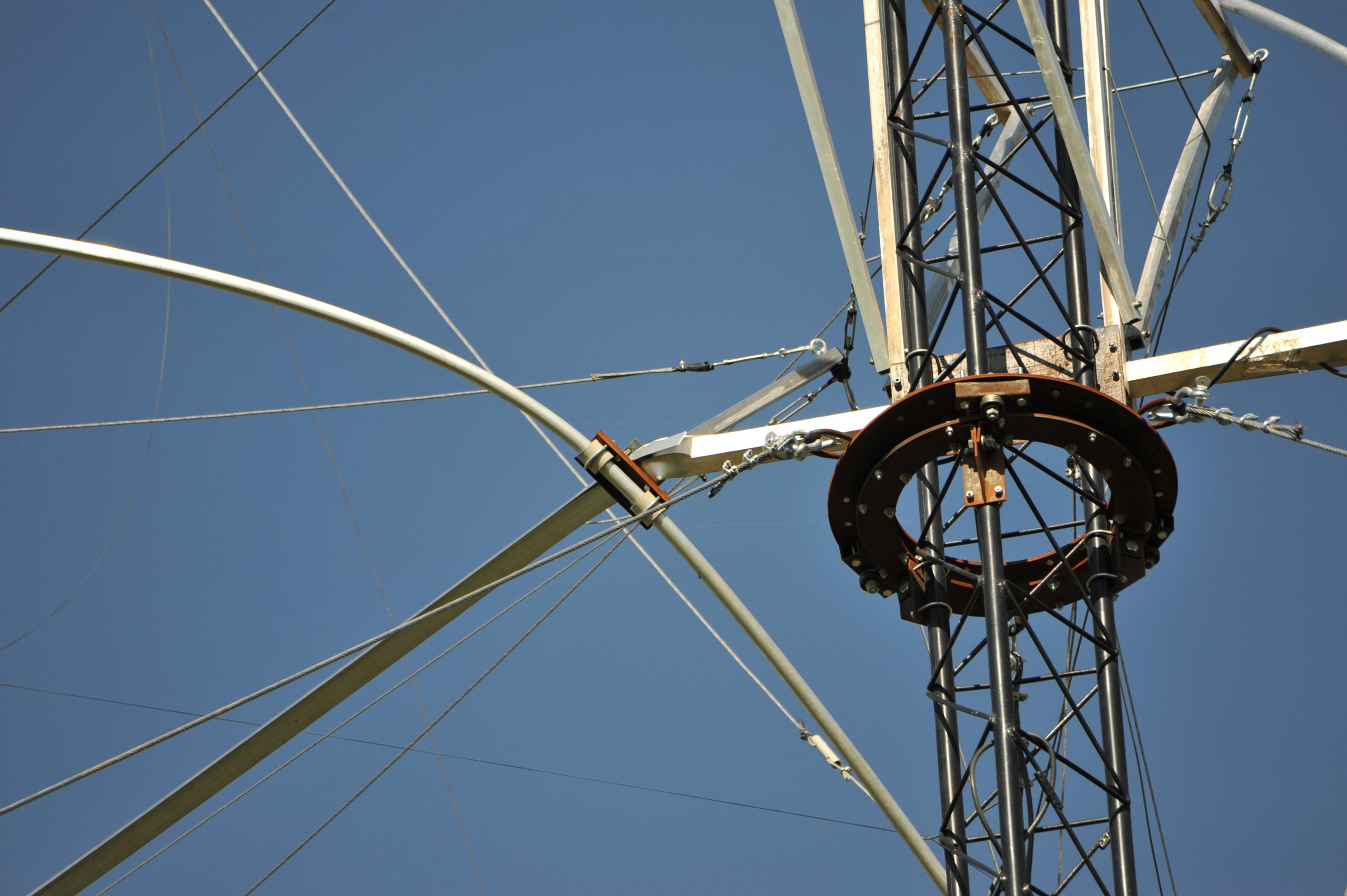
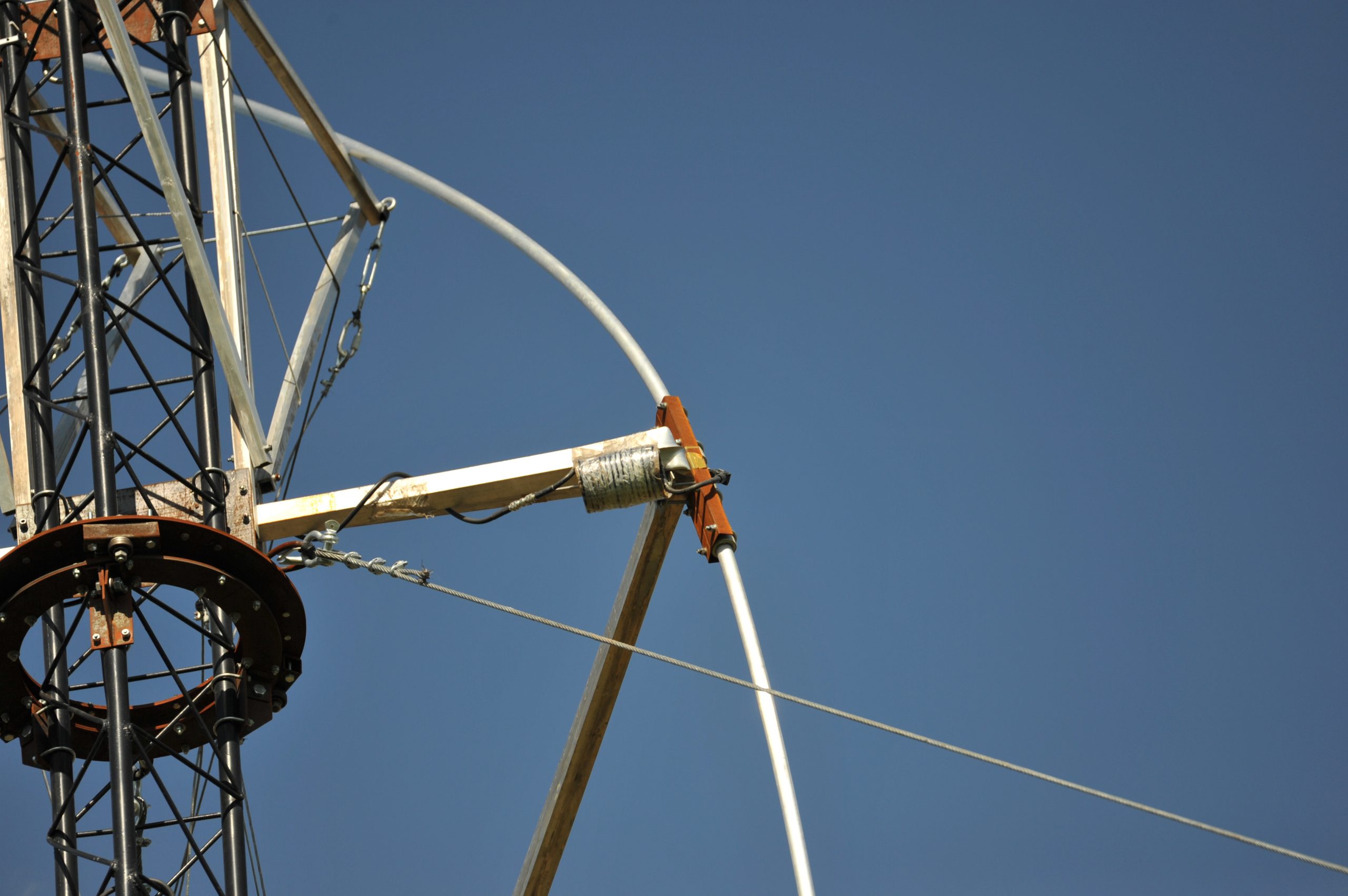
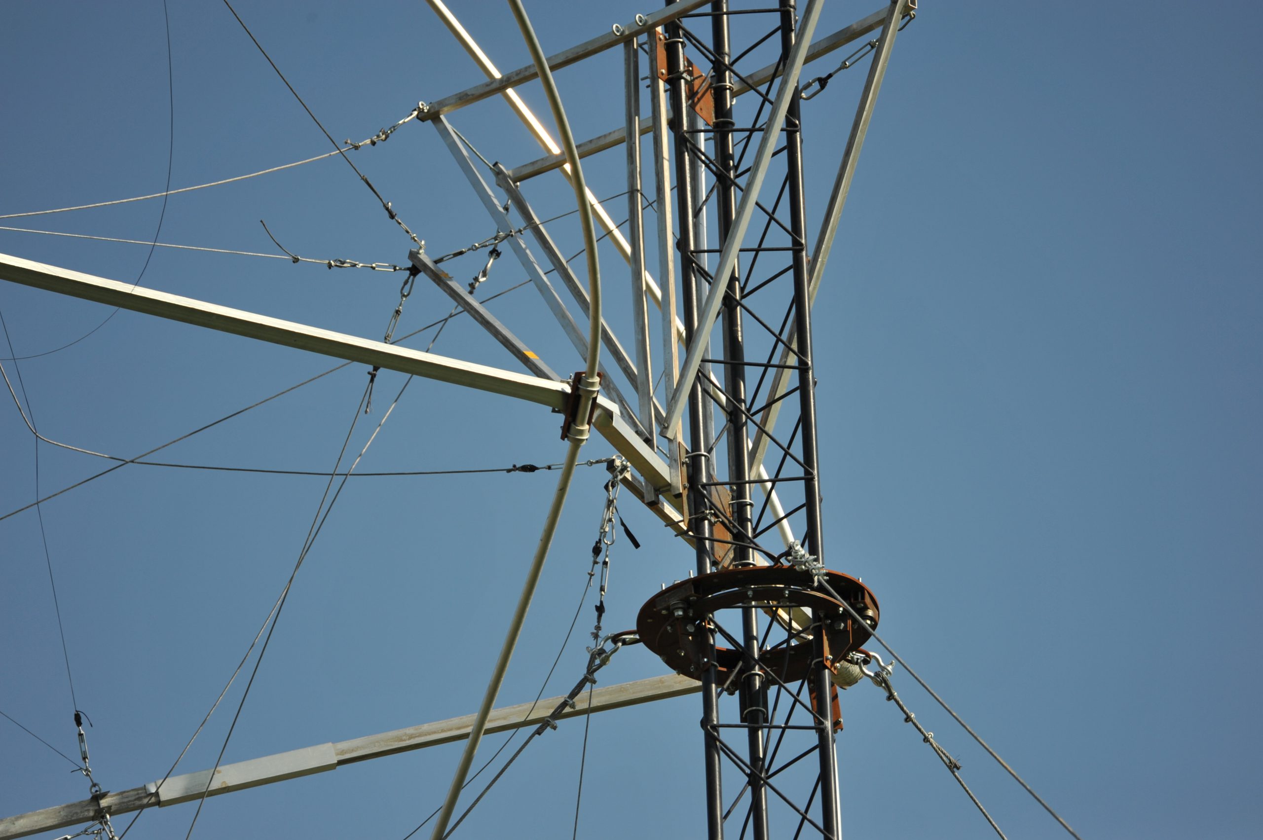
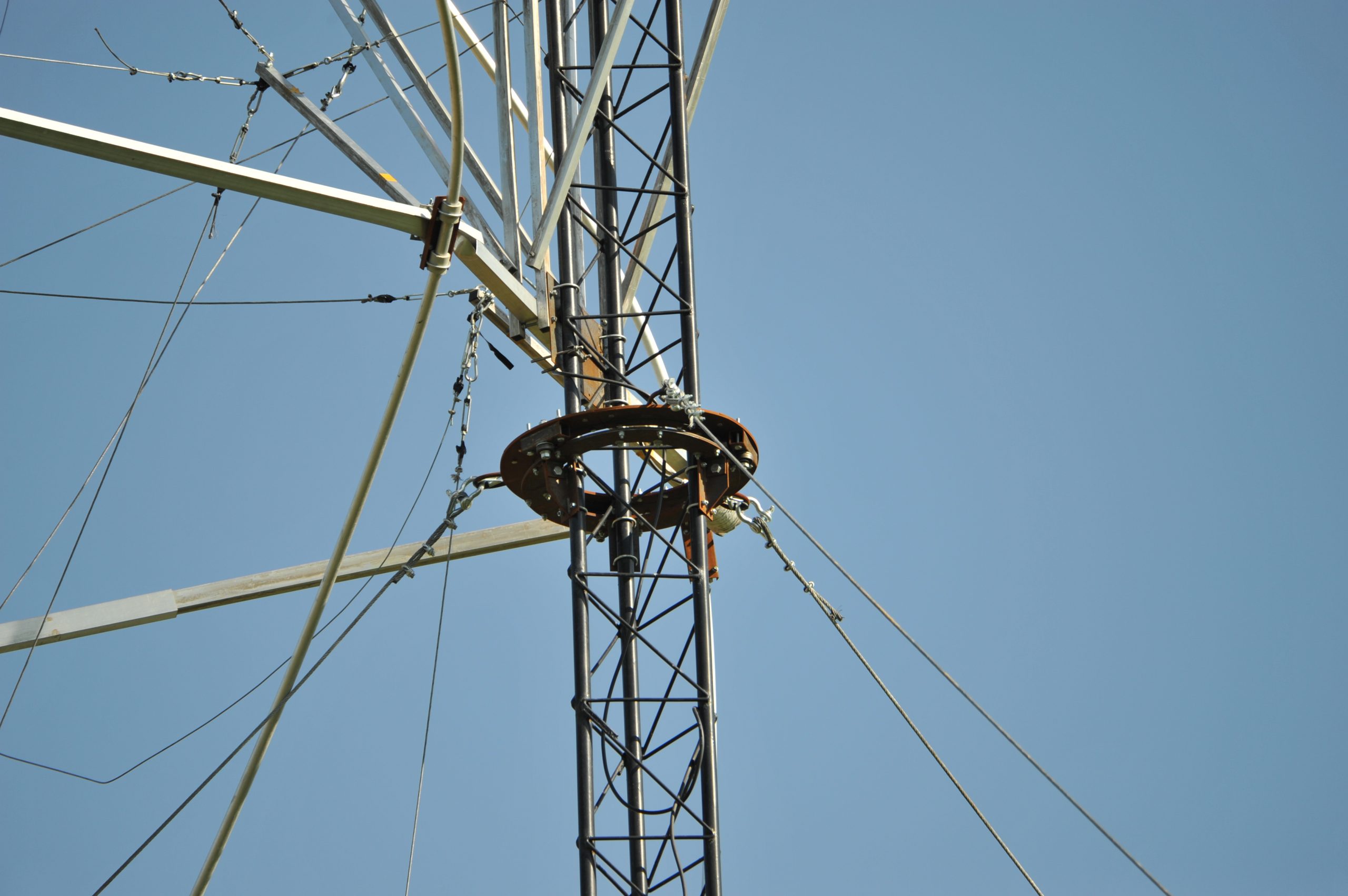
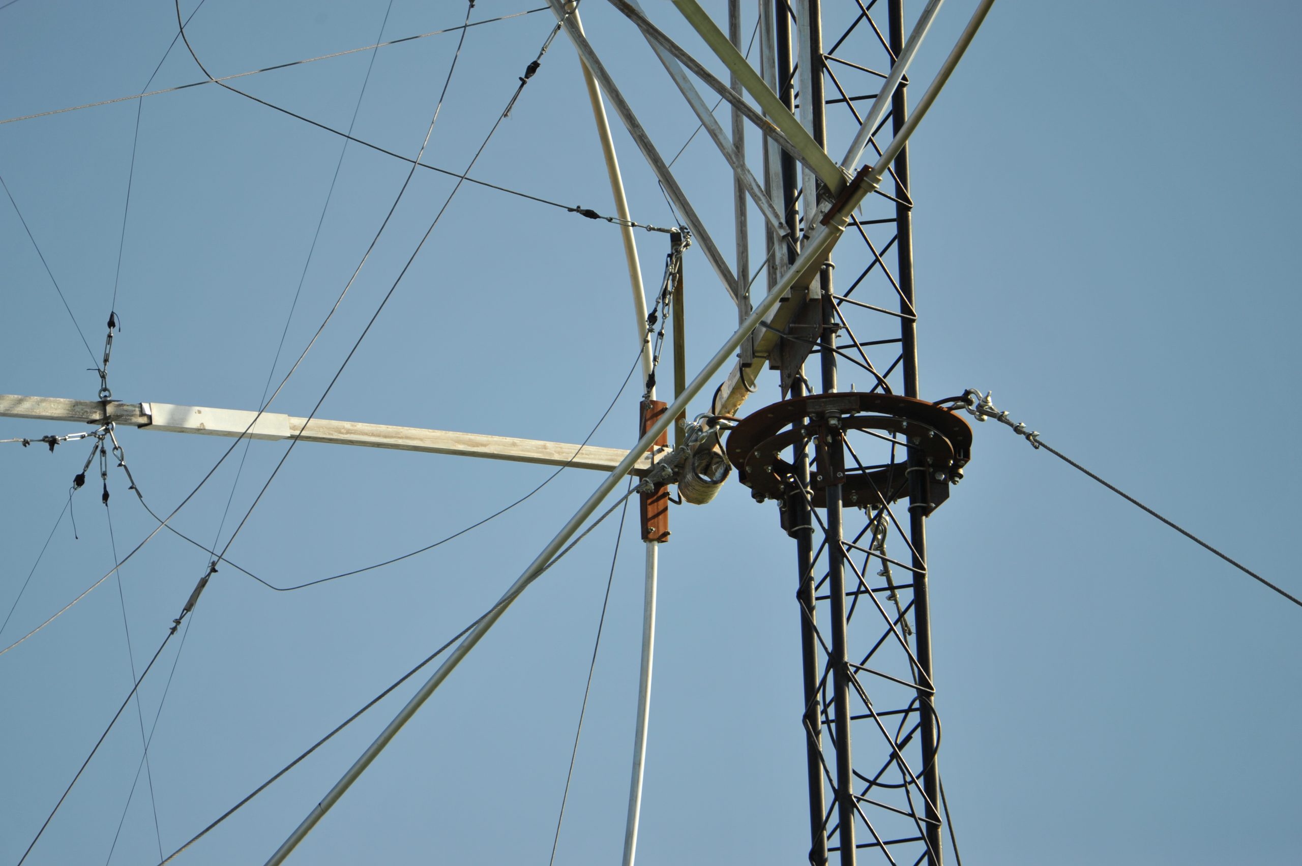
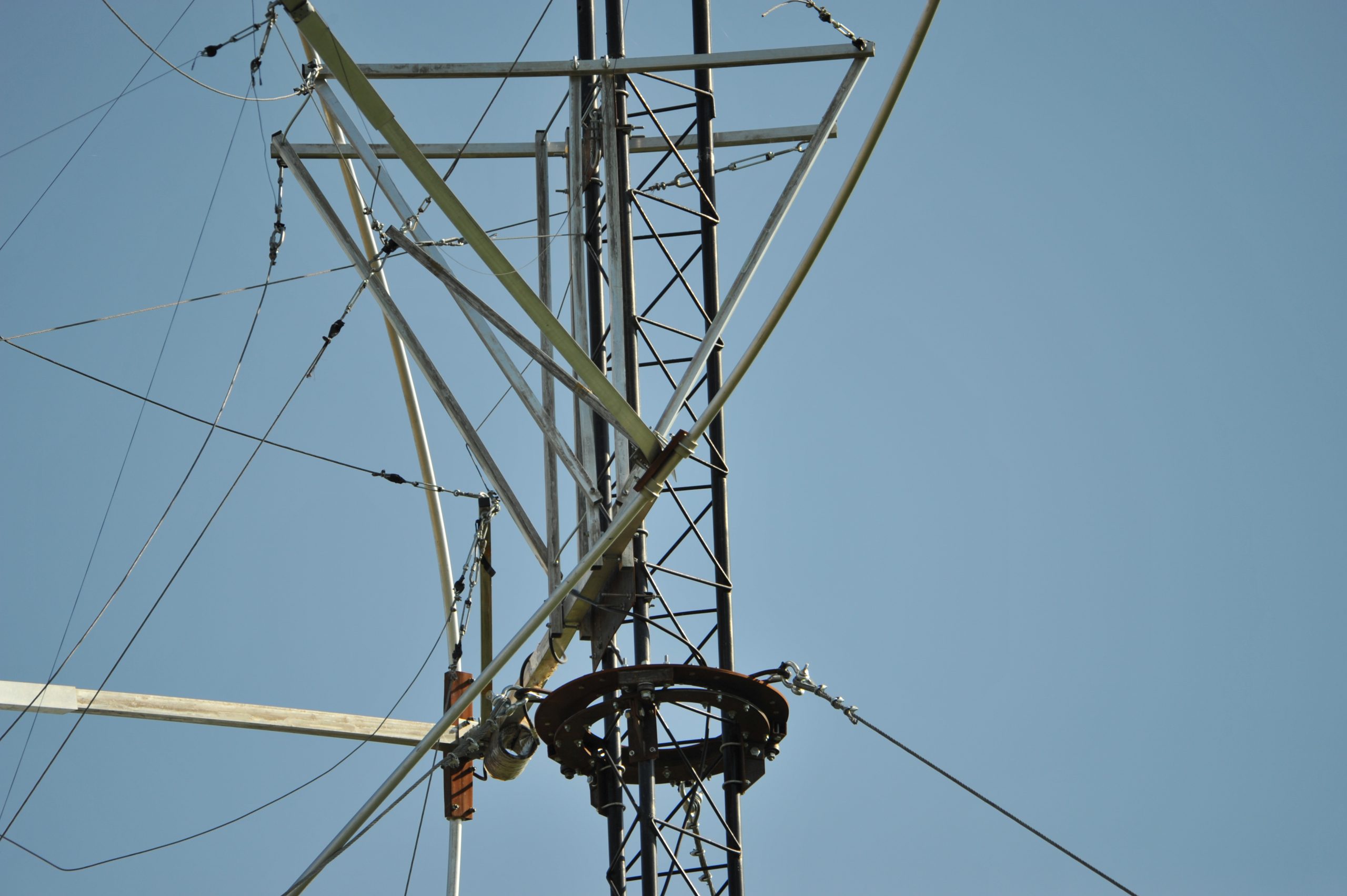
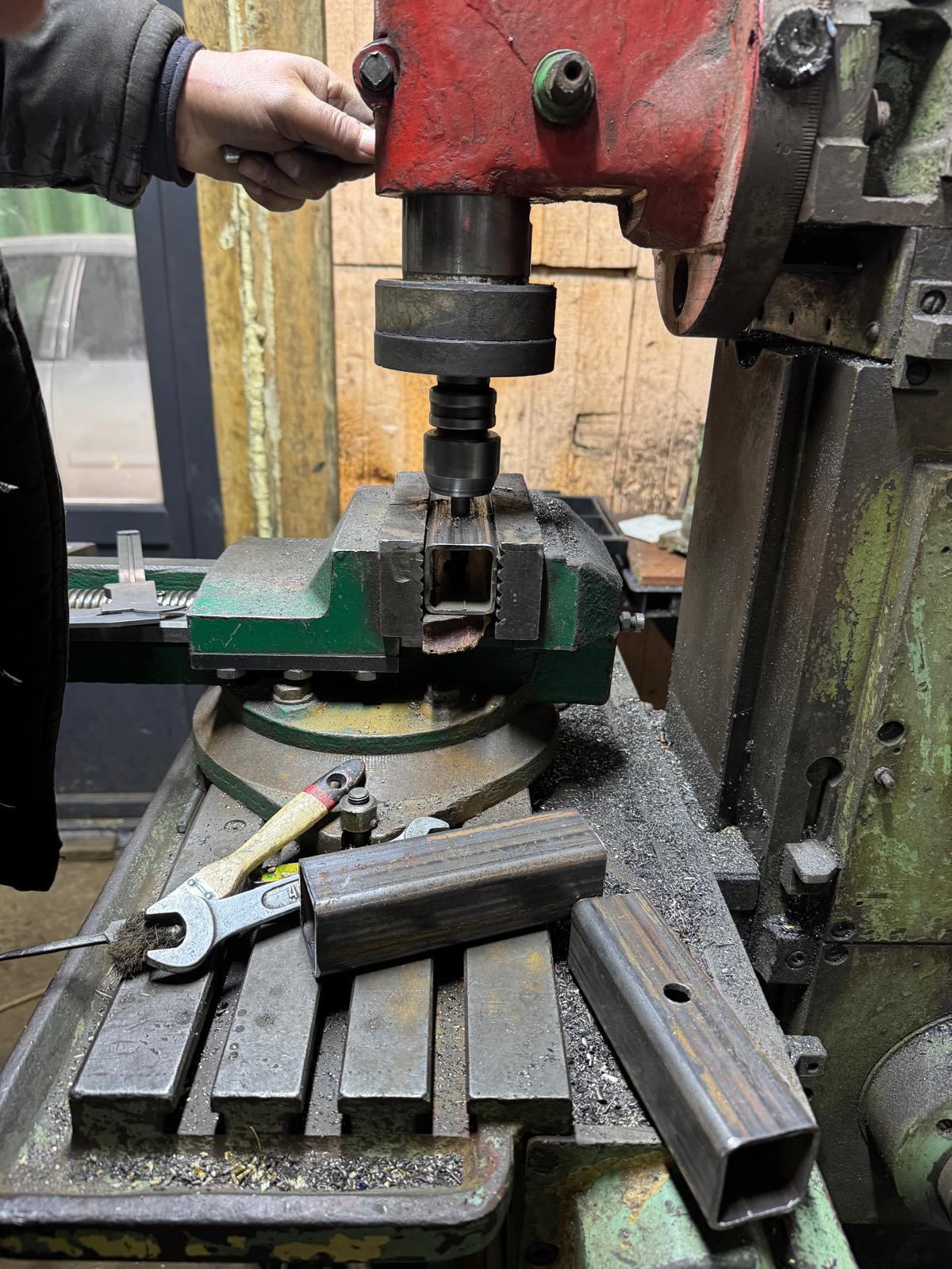
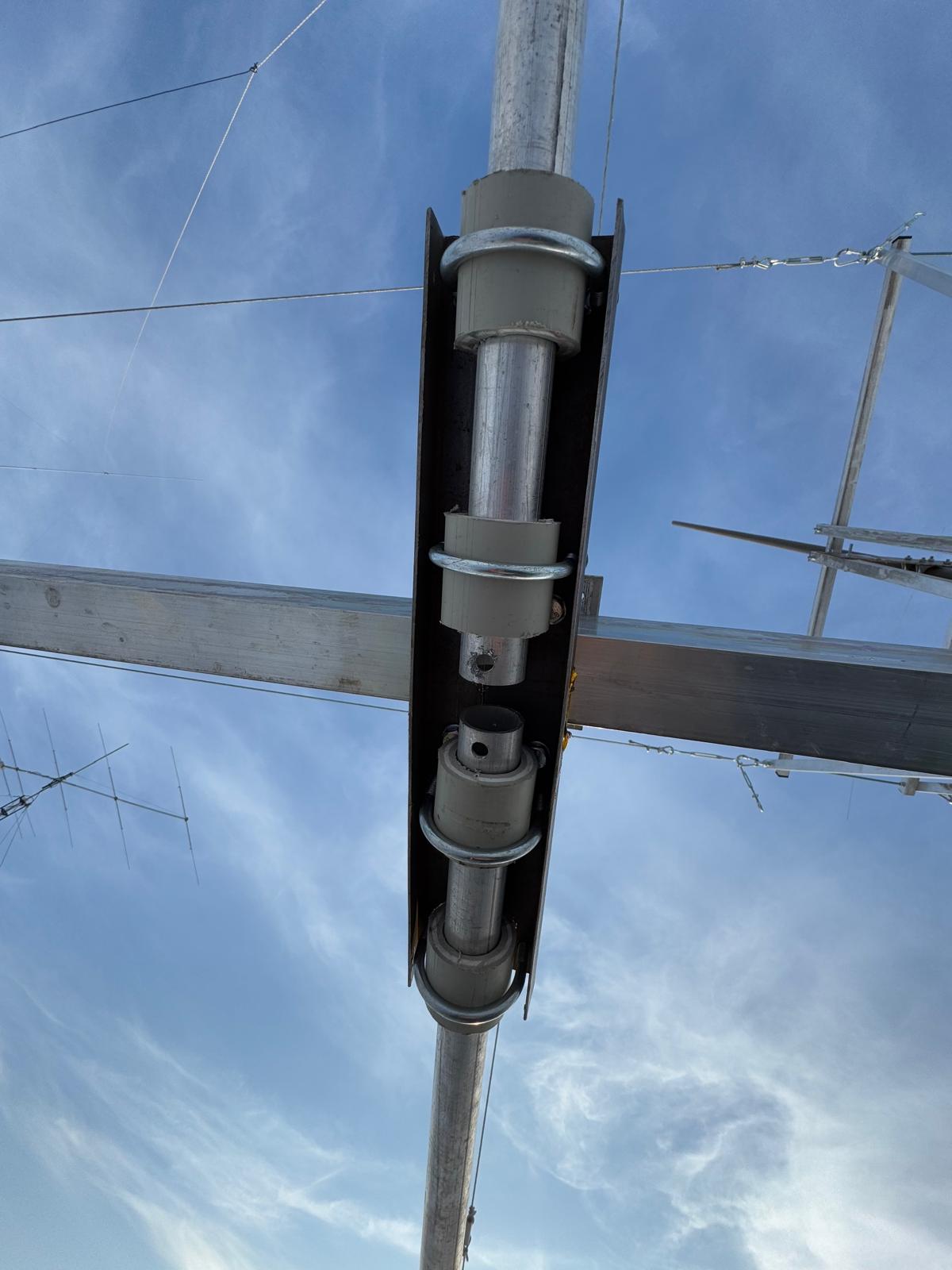
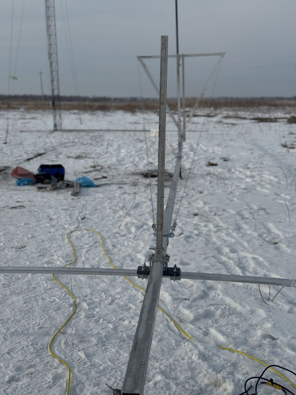
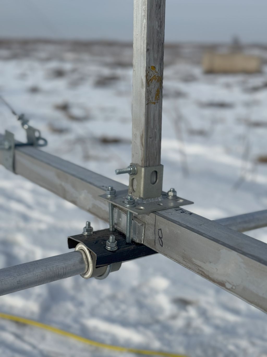
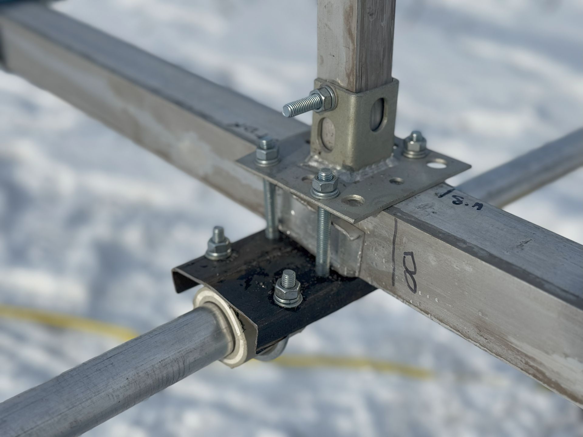
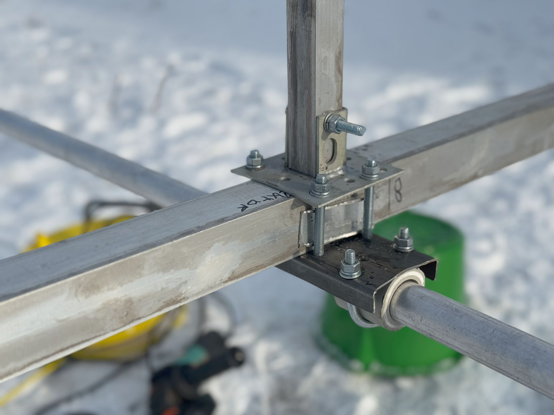
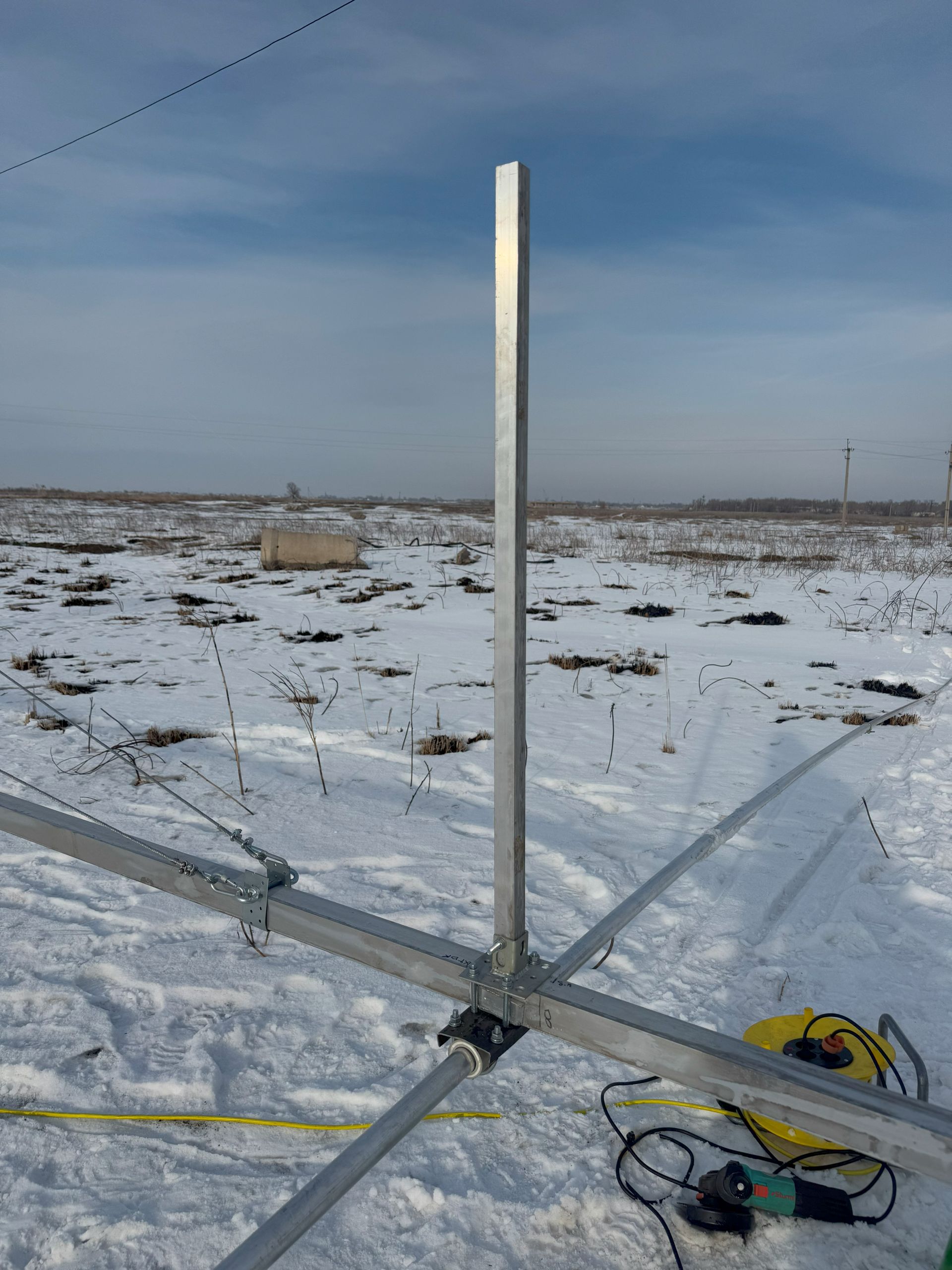
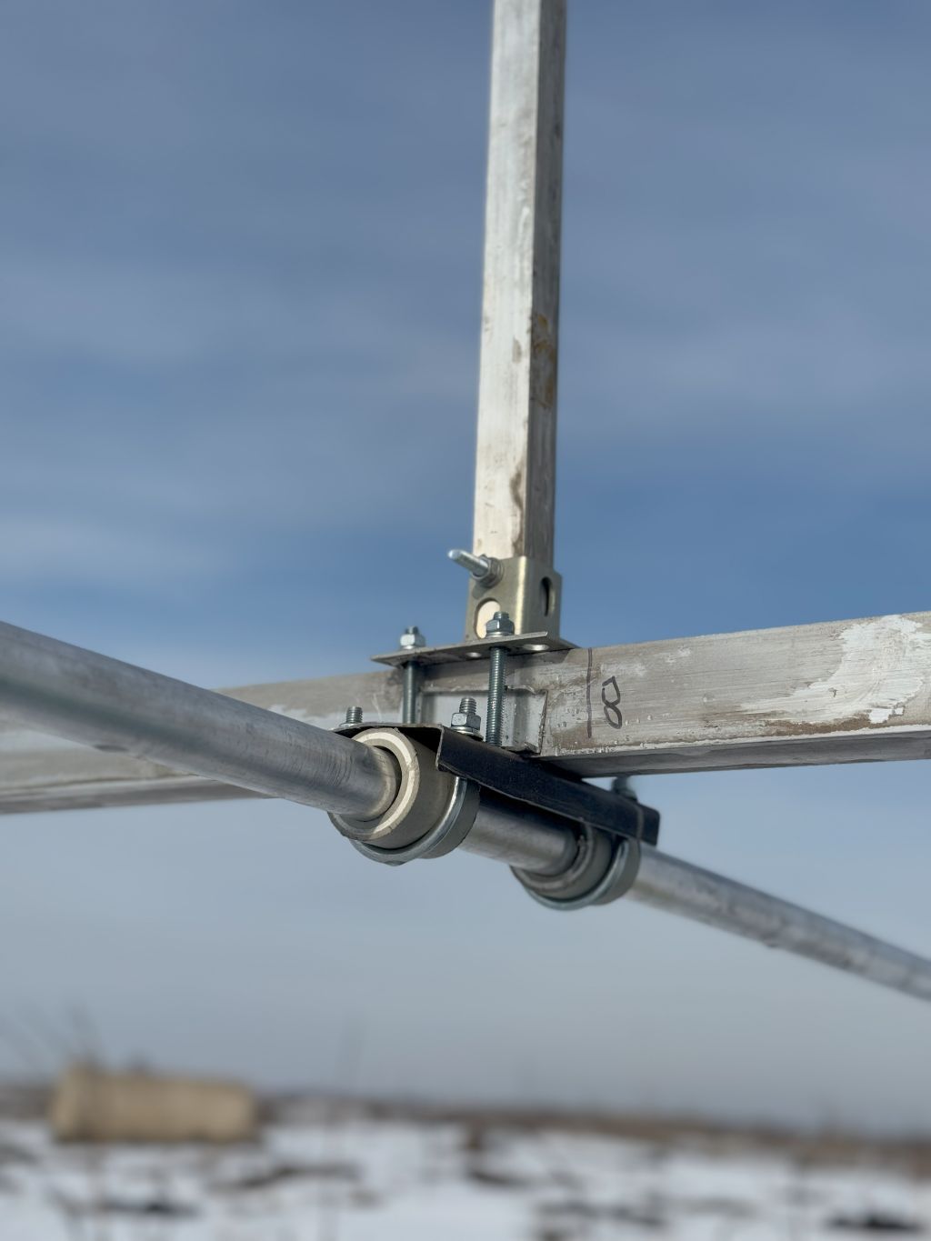
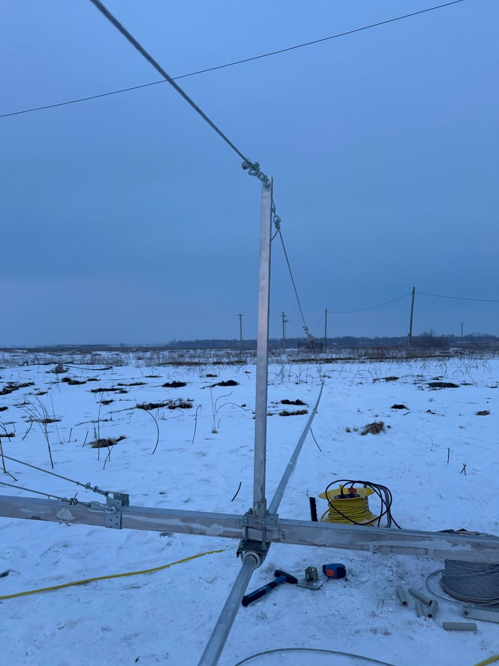
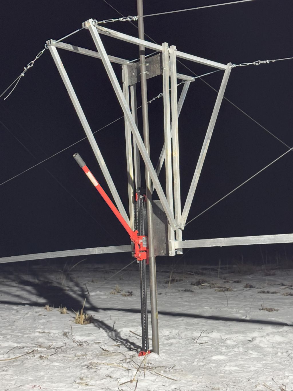
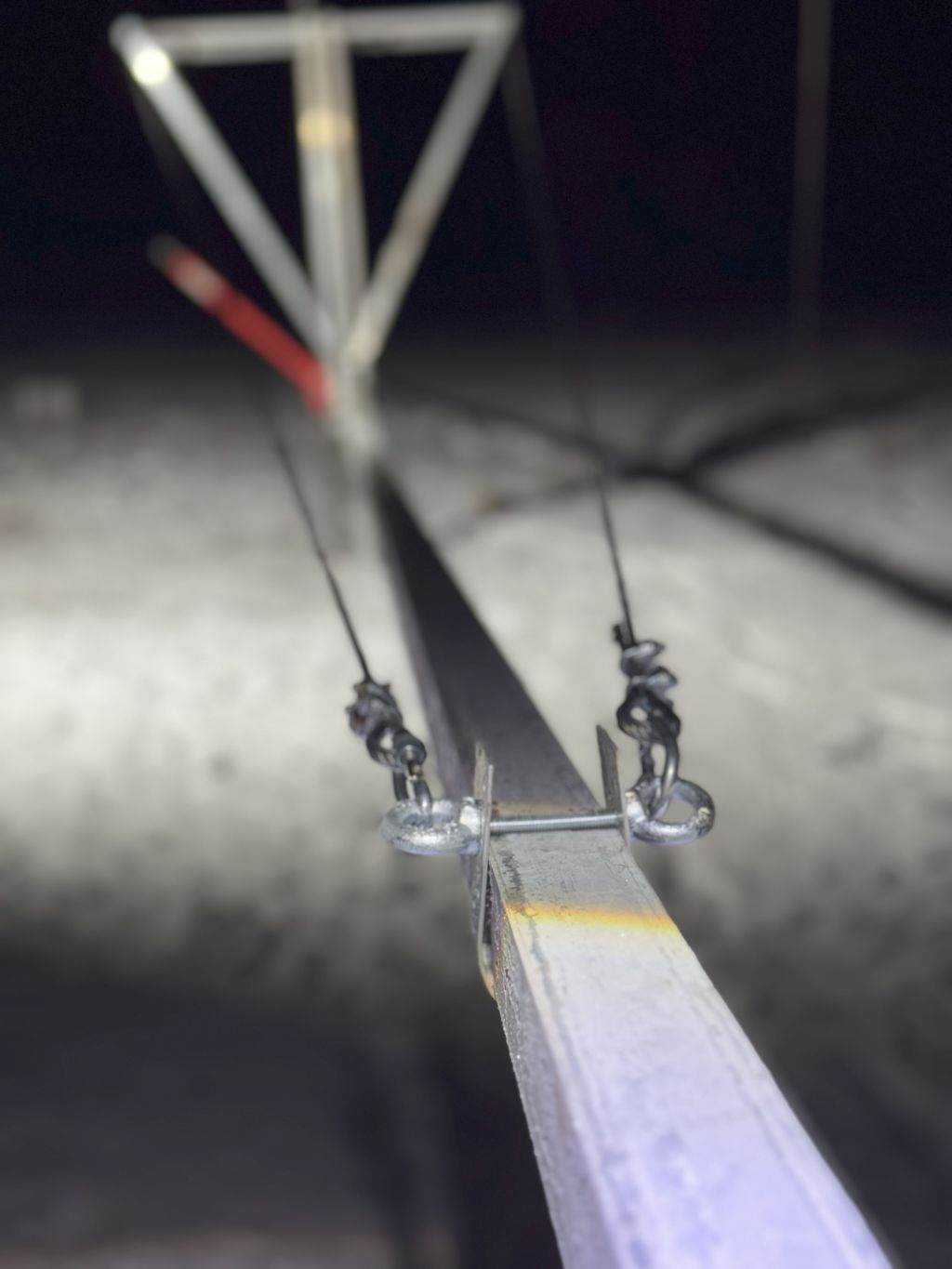
Making the rotator
Since the rotator was the last major undone element of the antenna, most of the time was spent on it:
- Assemblying
- Fighting the lose chain that tended to drop and stuck the rotator
- A couple of times, the mount for the rotator motor was completely bent and a rework was required because of the fallen chain but still turning the motor due to the lack of feedback that the chain was actually off already
- Multiple designs were trialed to keep the chain from being too loose and falling
- Several adjustments to the larger chain star to make it less wobbly and thus losing the chain
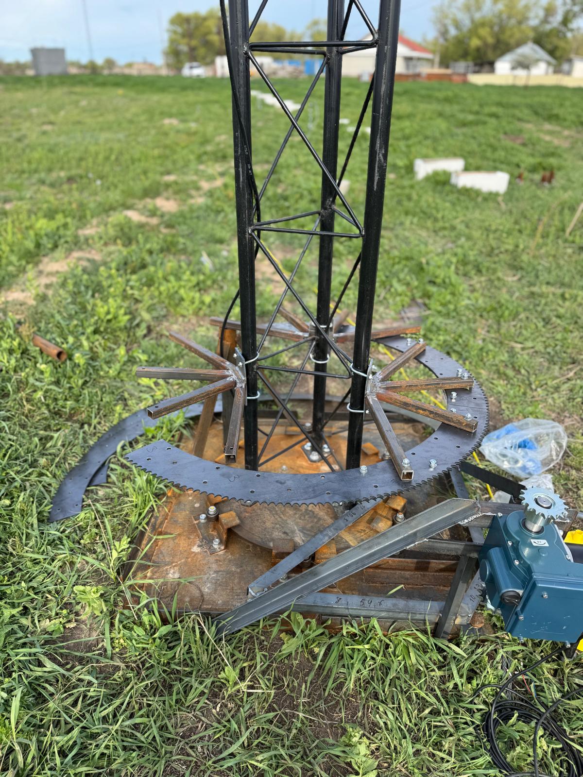
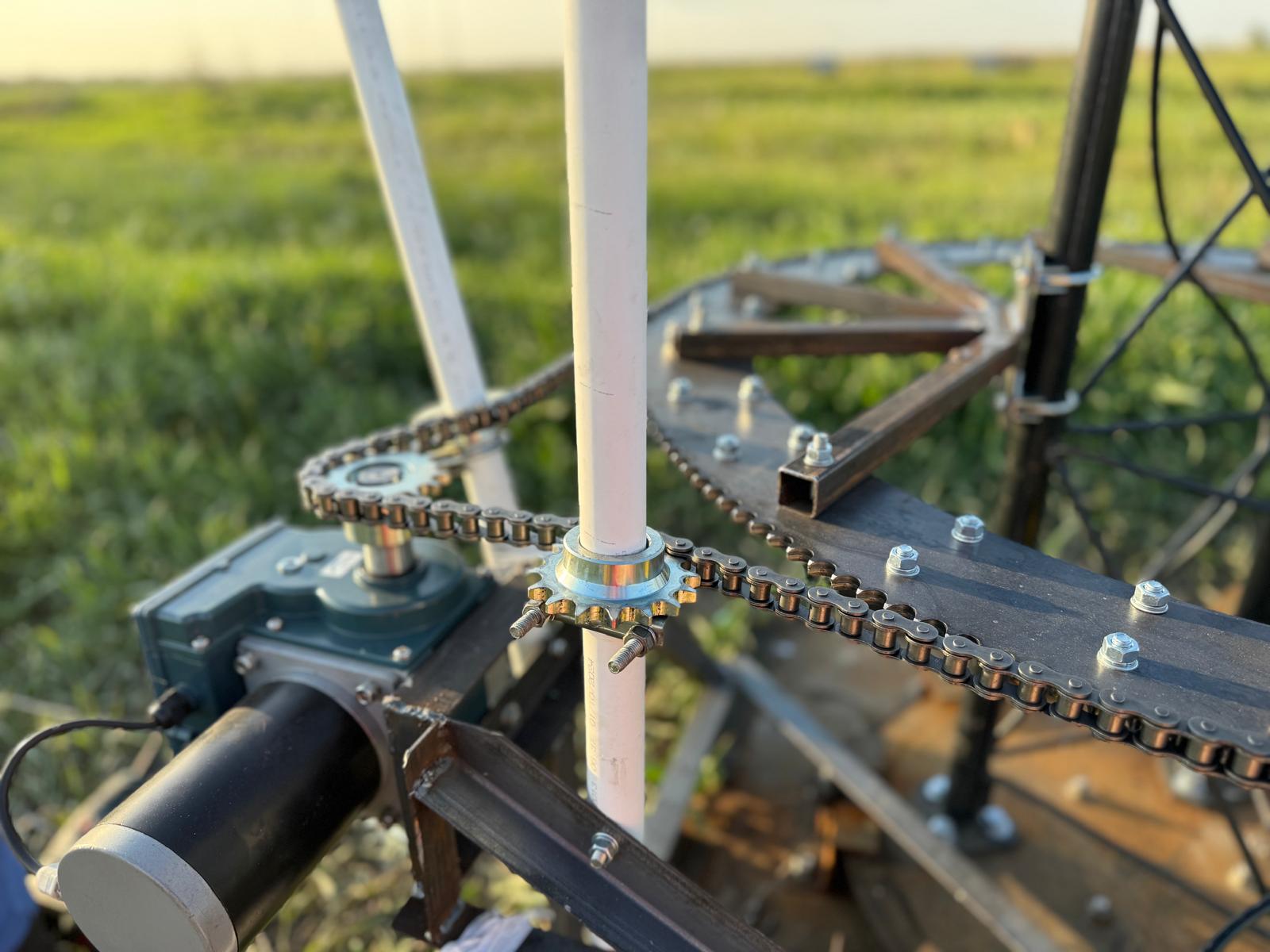

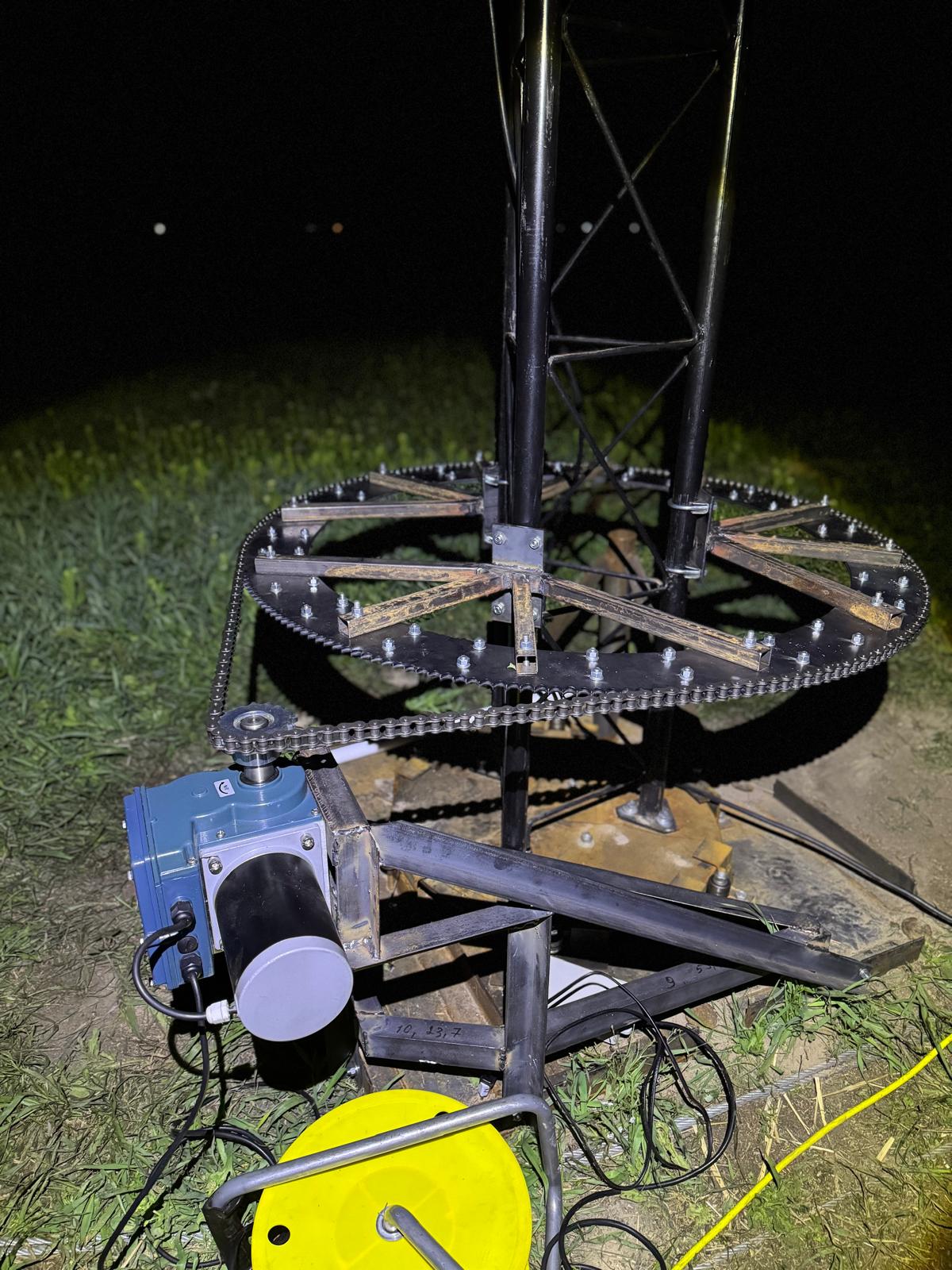
After trials and errors and twice-bent and nearly broken mount, this design has been working for the last two weeks:

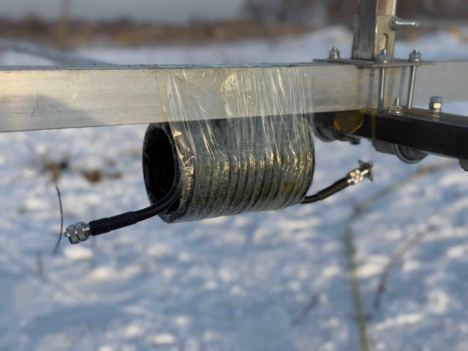
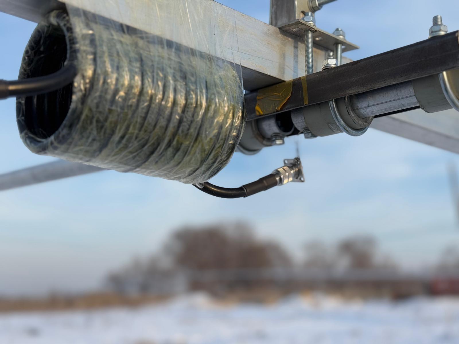
Remote control for the rotator
Since it is a remote QTH station, the remote control for the rotator is as essential as a rotator itself. The task is immediately split into several subtasks:
- Control of the motor of the rotator in both directions
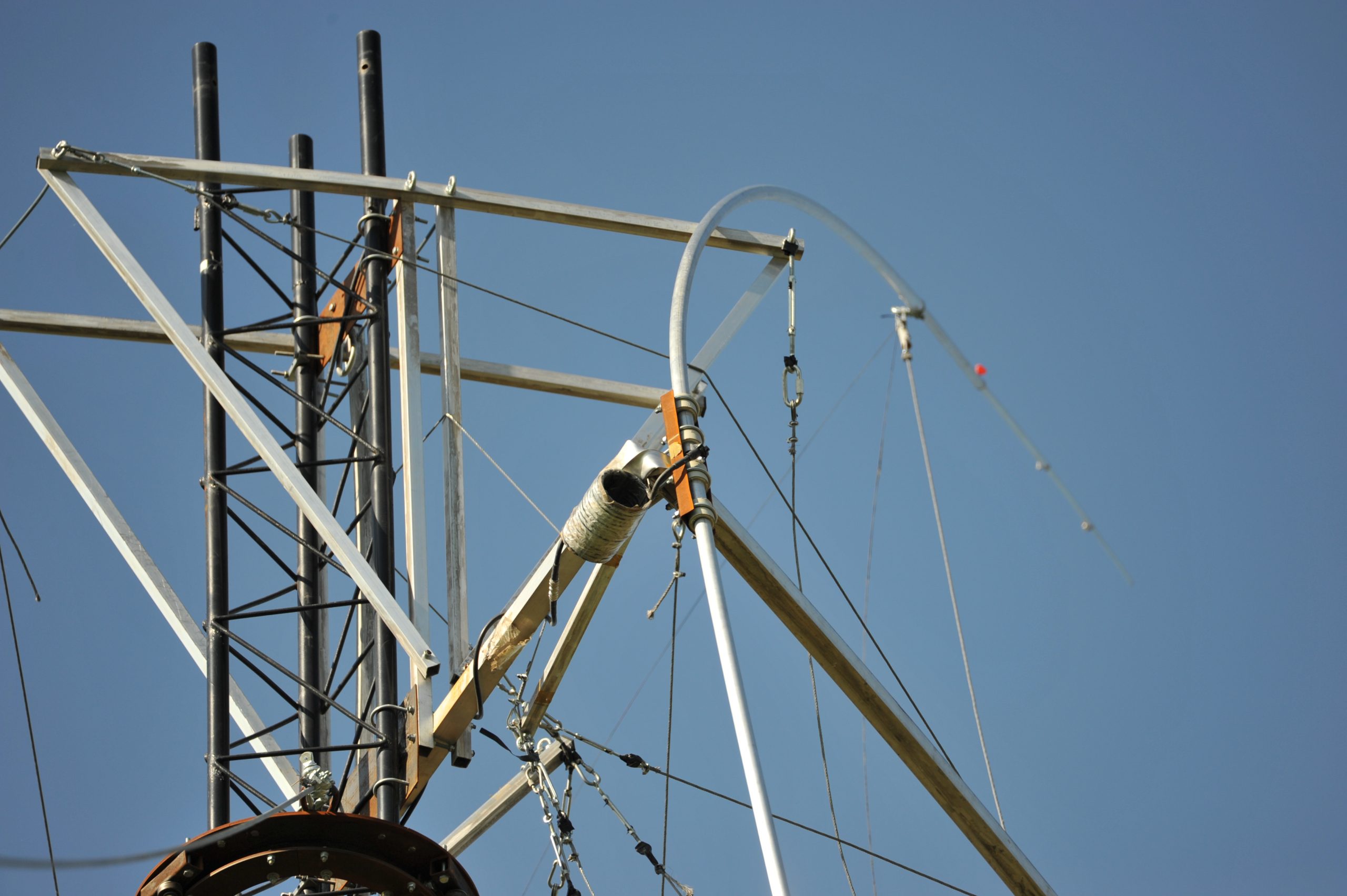
- Direction of the mast measurement
- Communication with the RCU (central remote control unit) located in the 20-foot container 50-60 meters away from the mast
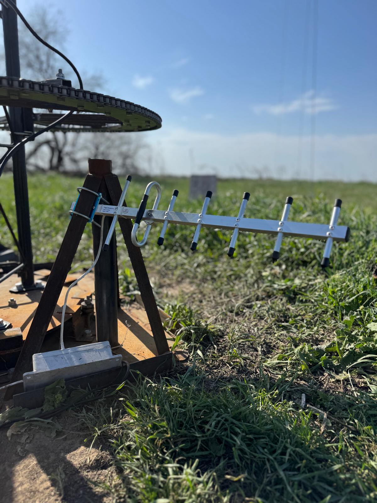
- The direction is measured by Marvelmind HW v4.9 beacon. We have some spare left. It is an older beacon but it contains a magnetometer that we need
- Additionally, a web camera is installed on a mast and improvised “solar clocks” – white bricks with angles written on them. So, I can connect to a webcam and see where the antenna is heading

Everything works well now: the tower rotates, the direction feedback is done using the magnetometer with the backup based on the camera, and everything is remotely controlled.
- All three towers/rotators are controlled and switched automatically when the Icom-7300 (or any Icom) switches the band
- Rotator 1 is a Yaesu G-800DXA on a 10-meter tower with a 10-meter 6-element OWA Yagi
- Rotator 2 is a Yaesu G-800DXA on a 18-meter tower with a 20-meter 4-element OWA Yagi. The 15-meter 4-ele OWA Yagi is still broken on the ground after the winch failure and dropped mast
- Rotator 3 is a homebrew rotator with a magnetometer as a direction measurement device for the 40-meter 4-element OWA Yagi

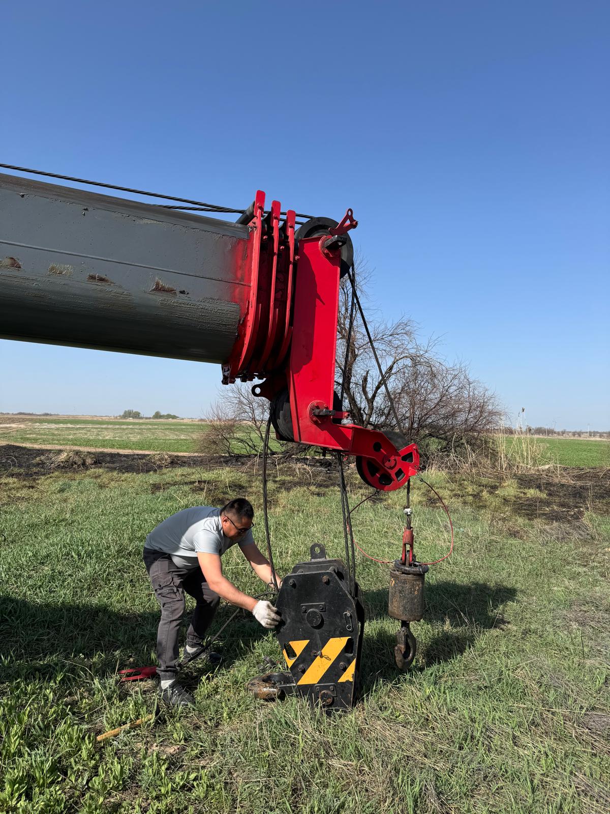
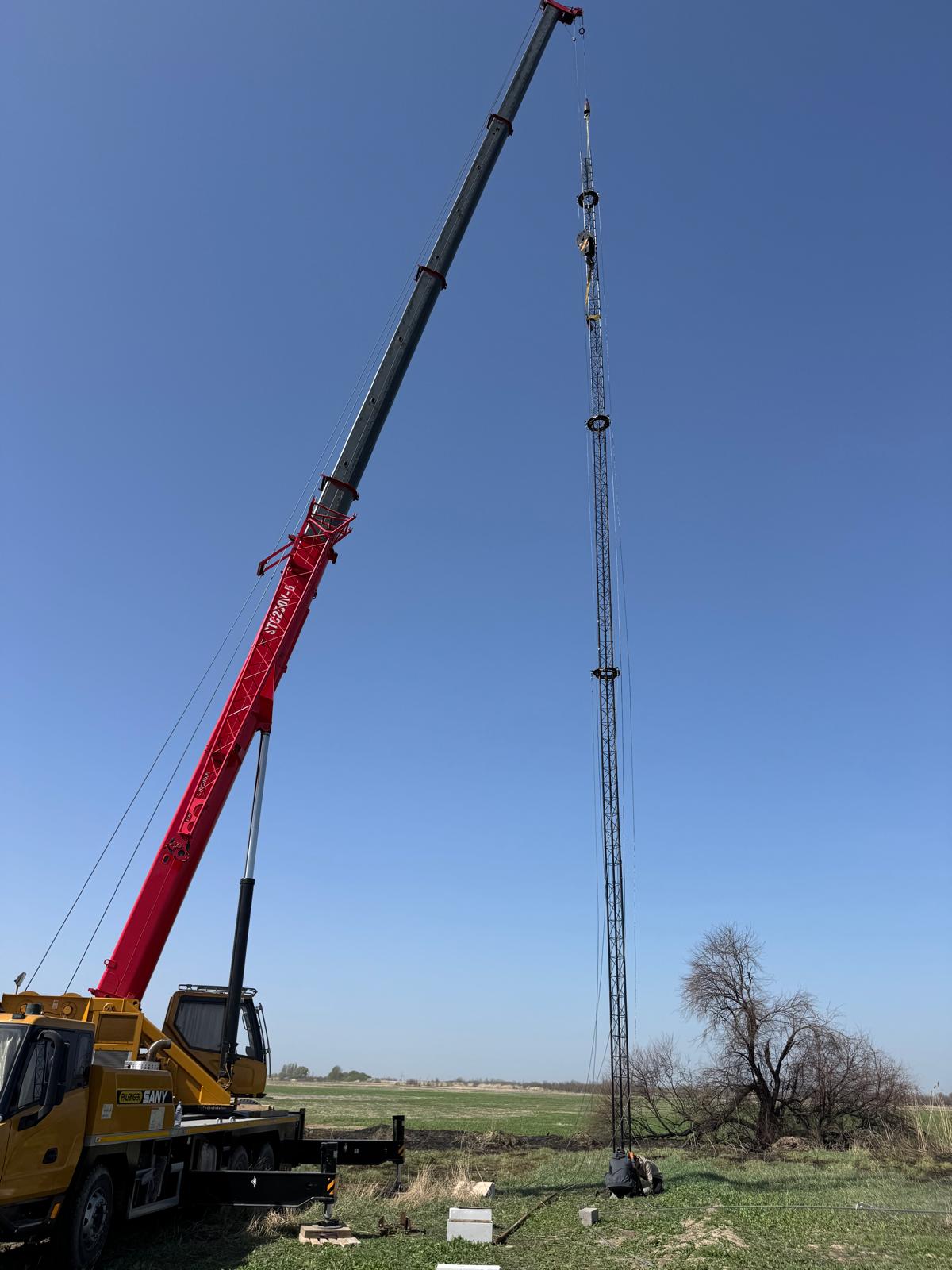
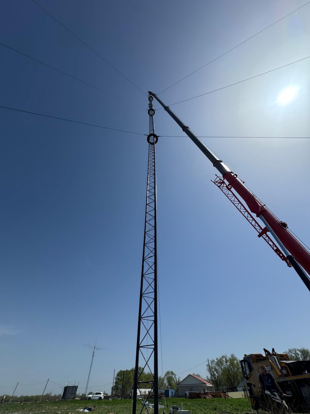
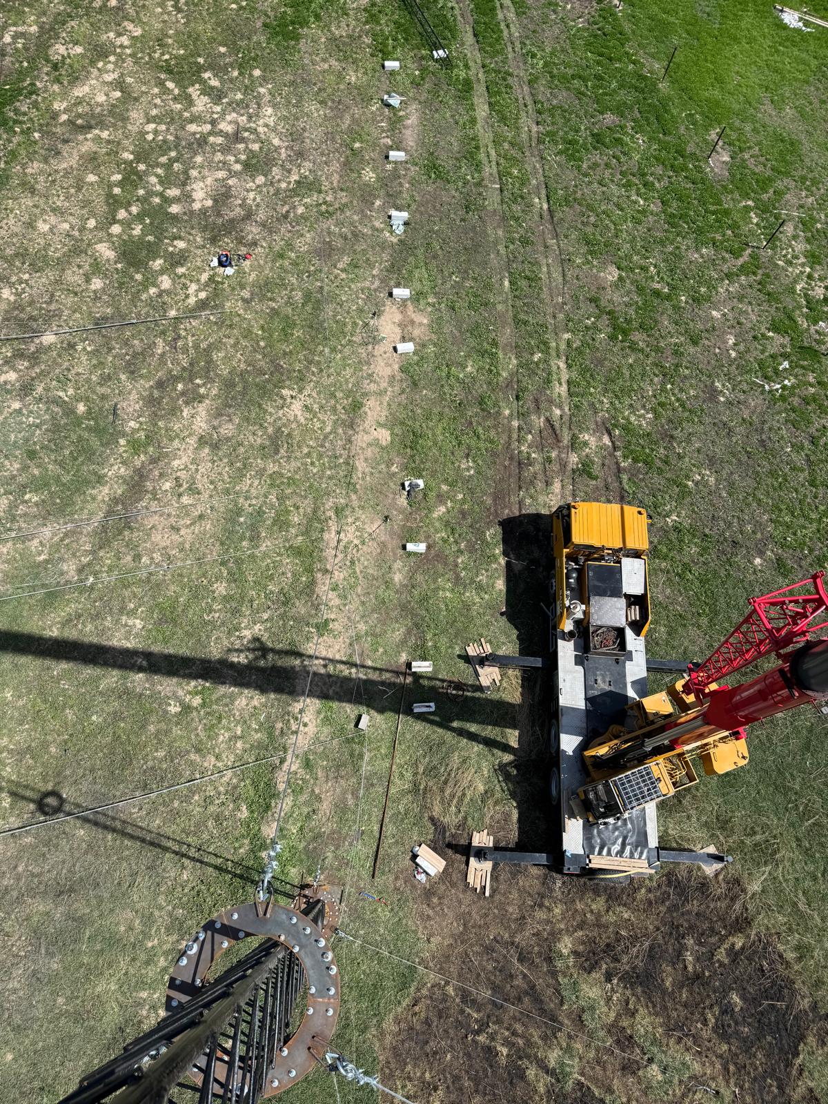
2025.Apr.13 - the Big Day 🙂
Many things can go wrong on the Big Day, from the weather to something basic but essential that is missing without a possibility to quickly find or replace. Thus, I prayed to all supporting gods so that thing would go weel 🙂
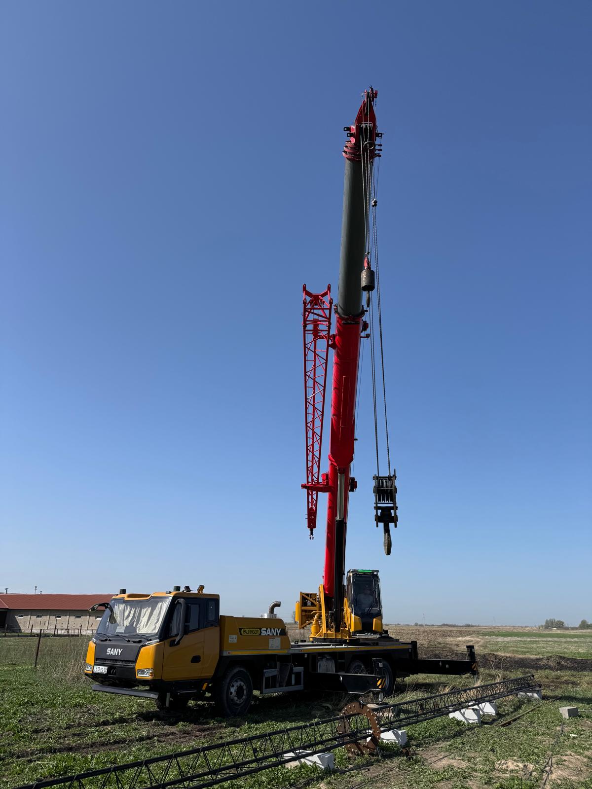
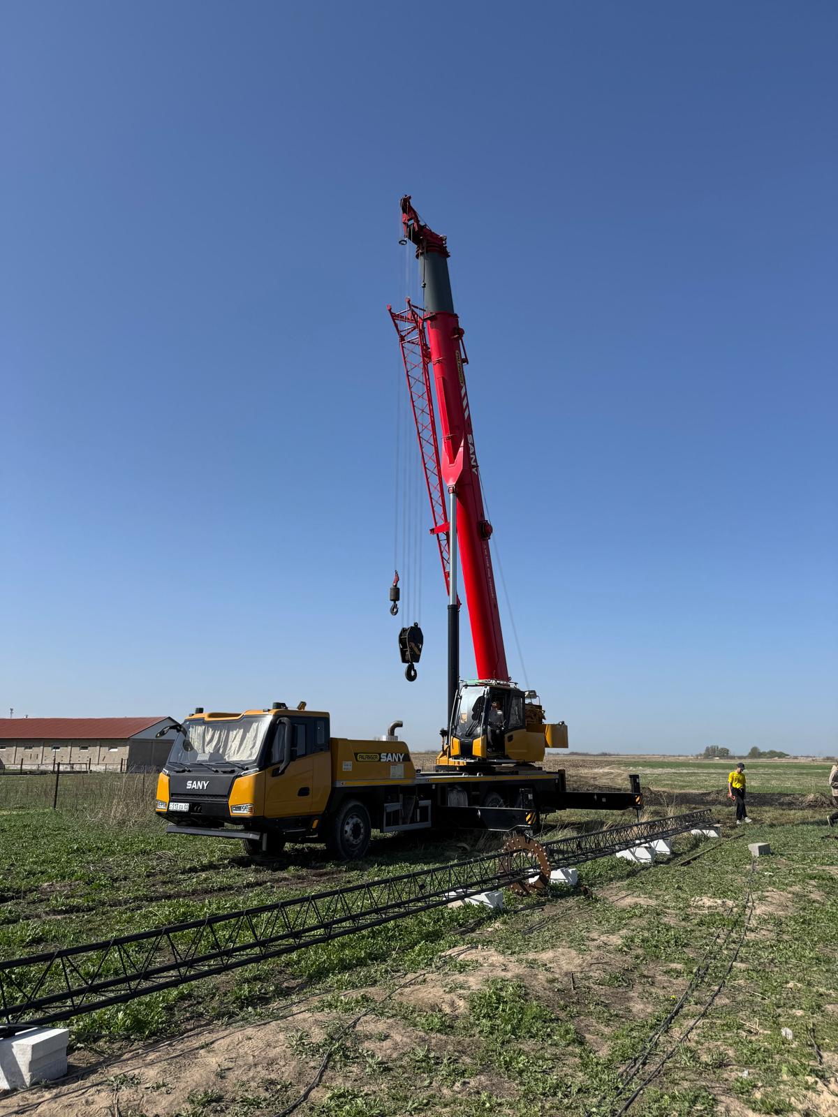
Crane
After a couple of months of searching, I finally found a crane with a reasonable price (~500 USD/8 hours). It was about two times more than my first limits (based on the asverised prices, which are a total fake), but 2-3 times lower than I was offered when I tried to scout for the options.
I almost selected another crane service, but then the guy tried to rest the fee at the last moment, etc. Luckily, I expected such behaviour and had two other options. Eventually, our crane-man did everything very well. So, I have a solution for the future, when needed.
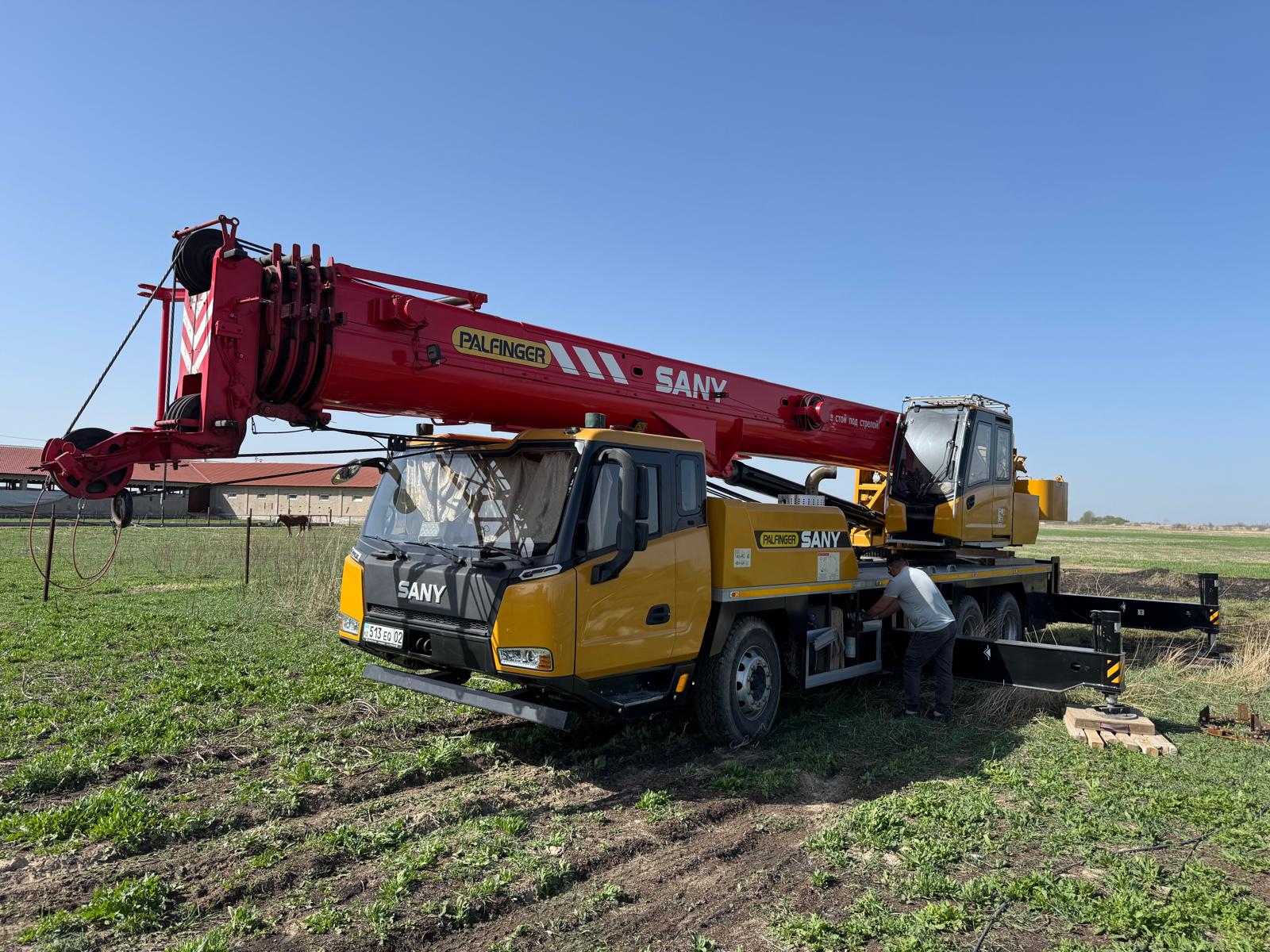
The cranes are measured in tons, whereas I was far more interested in the length.
This one has a 43-meter boom and with an add-on (for light weight) – up to 57 meters. Nice to know for future planning.
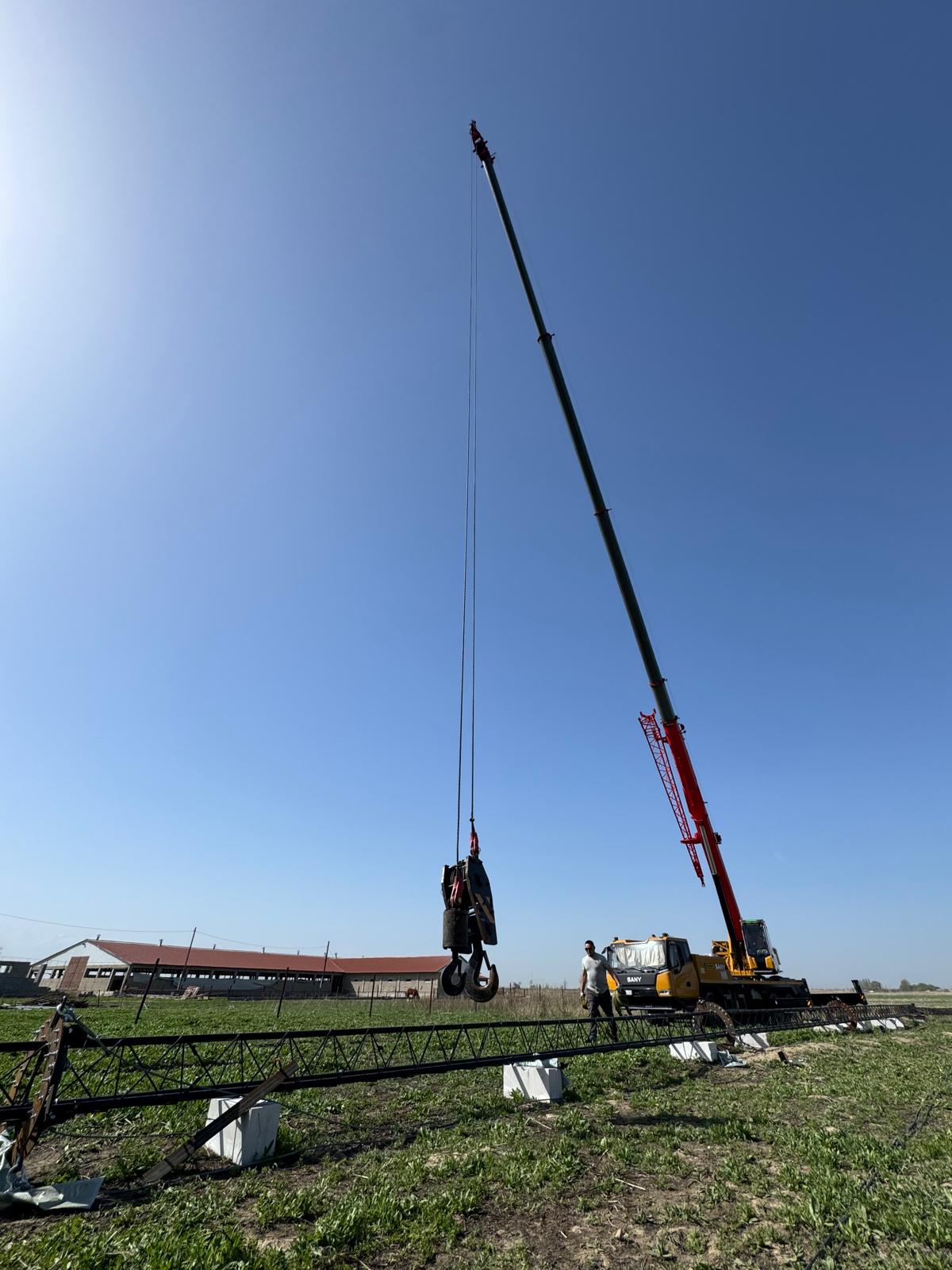
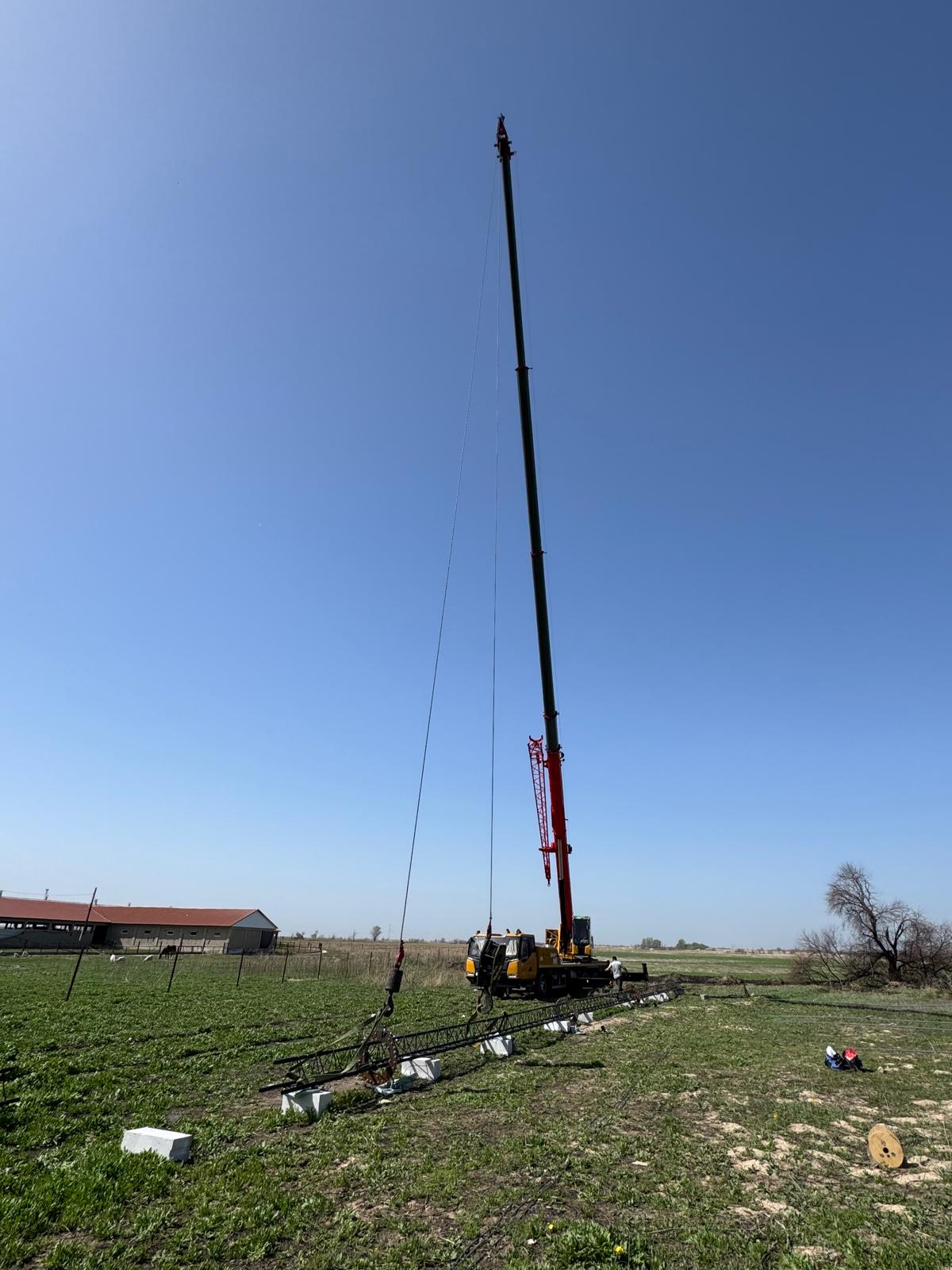
Risk of too much mast bending
There were multiple risks with the project in general and each step in particular.
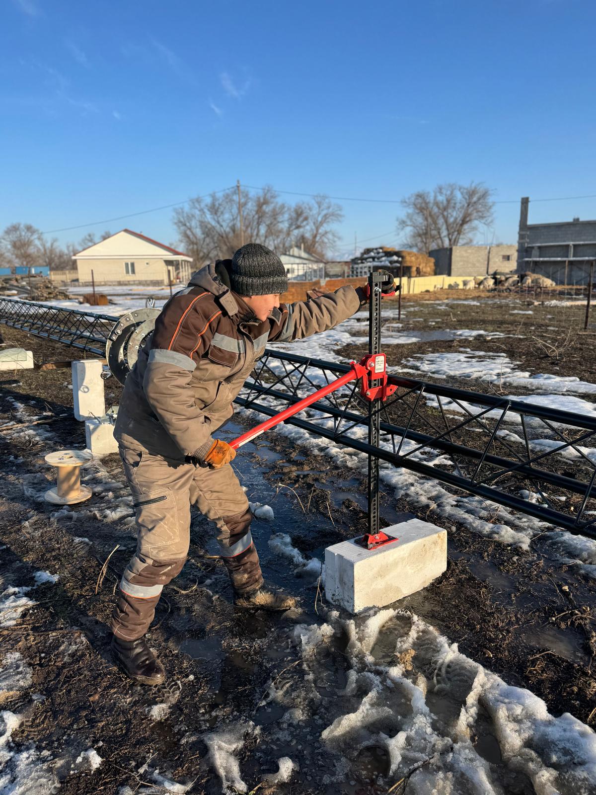
The first risk was the tower breaking or bending too much under its weight. To minimize the risks, we tested the 30-meter by using a car jack more than a month ago. It bent but reasonably. Thus, to play super-safe, we installed the 30-meter tower instead of the 42-meter tower that was built and prepared.
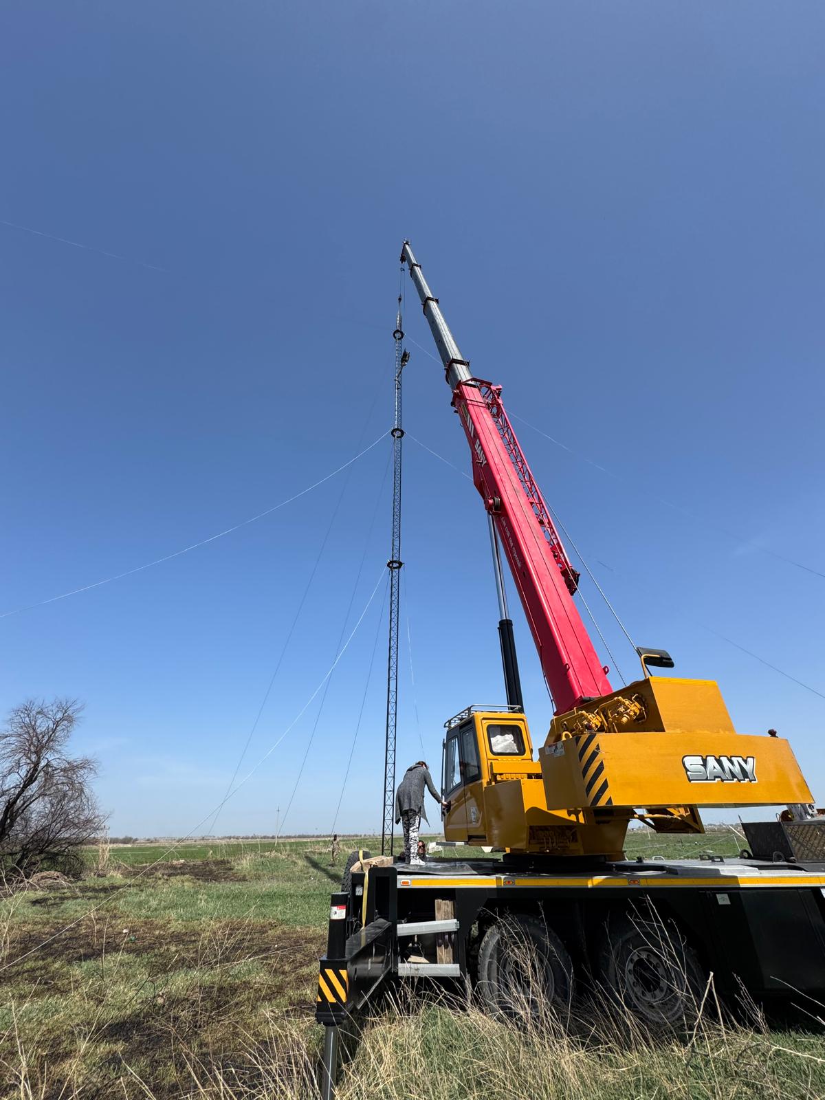
Everything went well and smoothly.
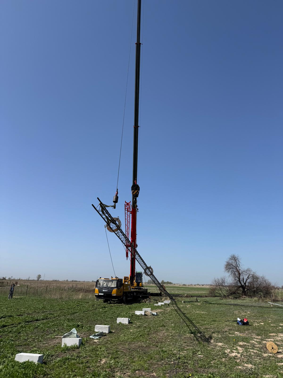
I didn’t know that the crane had two independent lines and hooks. That is a huge help. If I had known, we would have gone straight to the 42-meter variant, which would have supported the mast in two points and significantly reduced the bending.
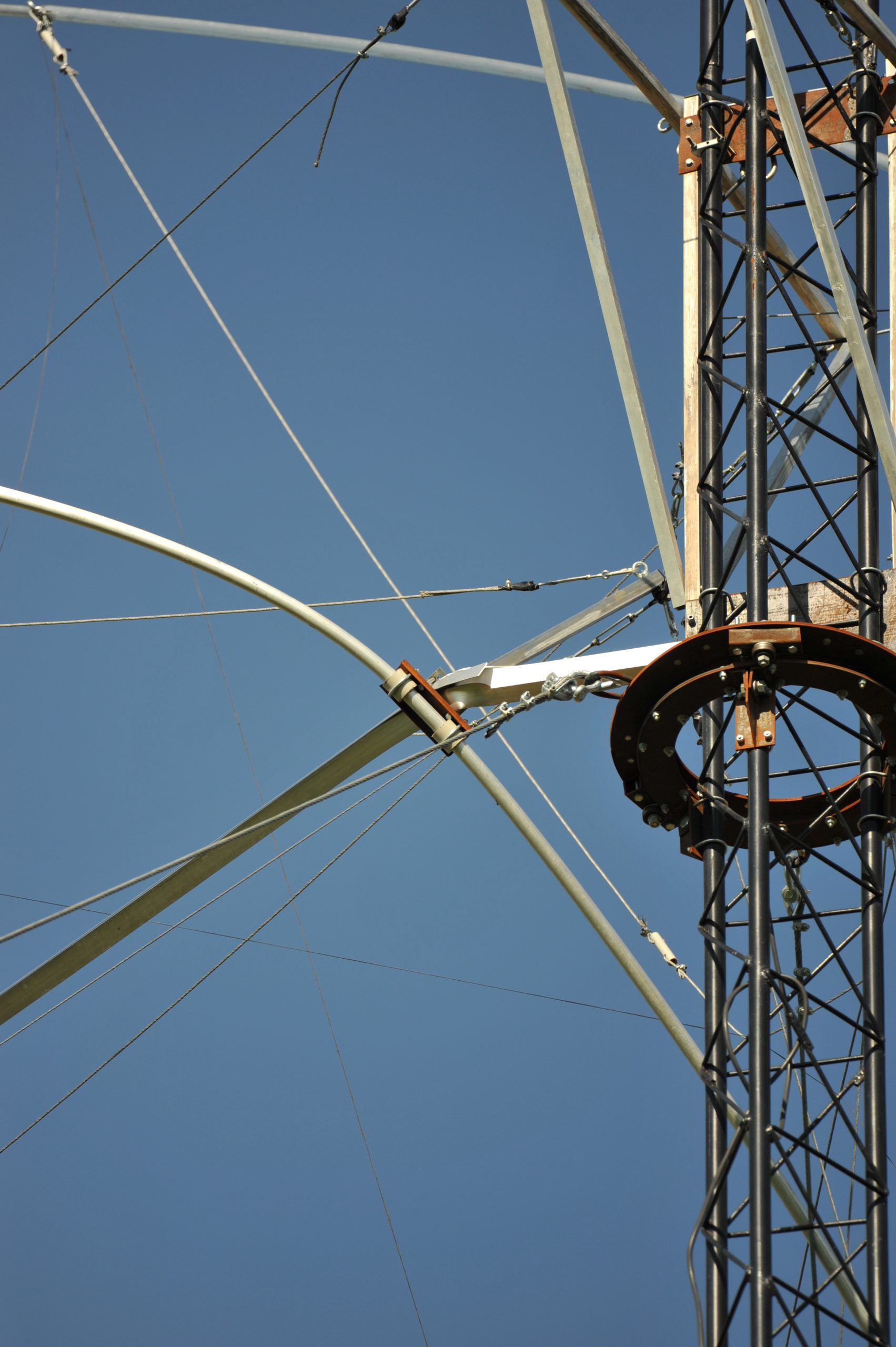
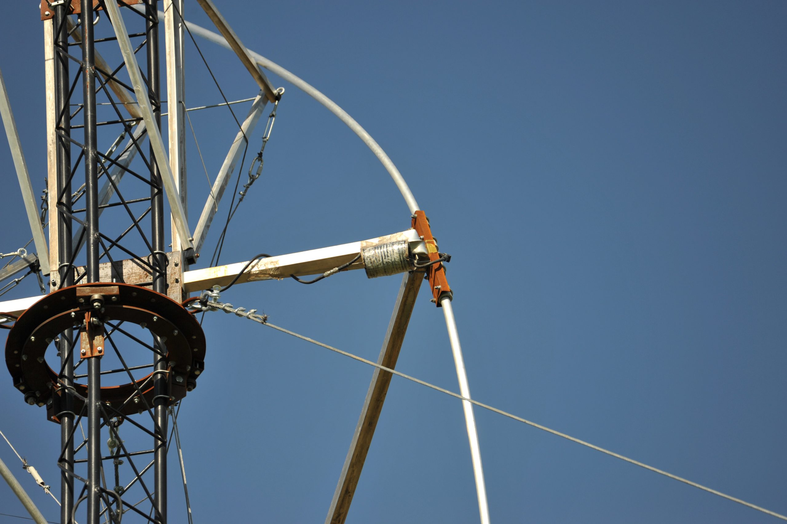
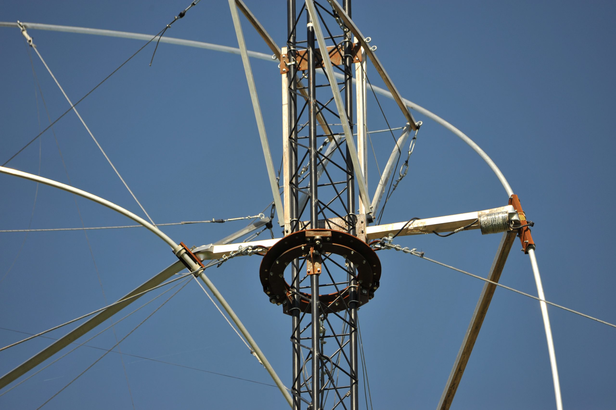
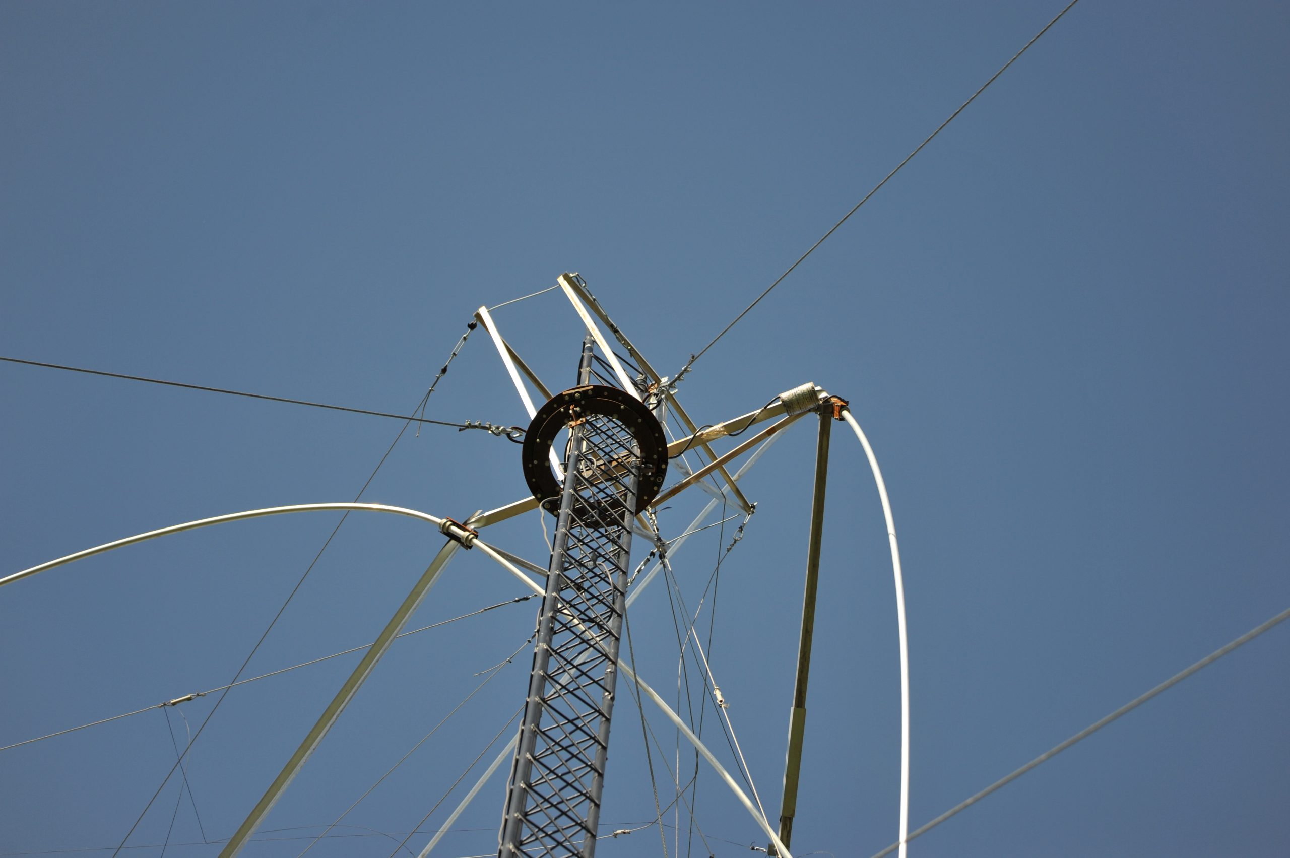
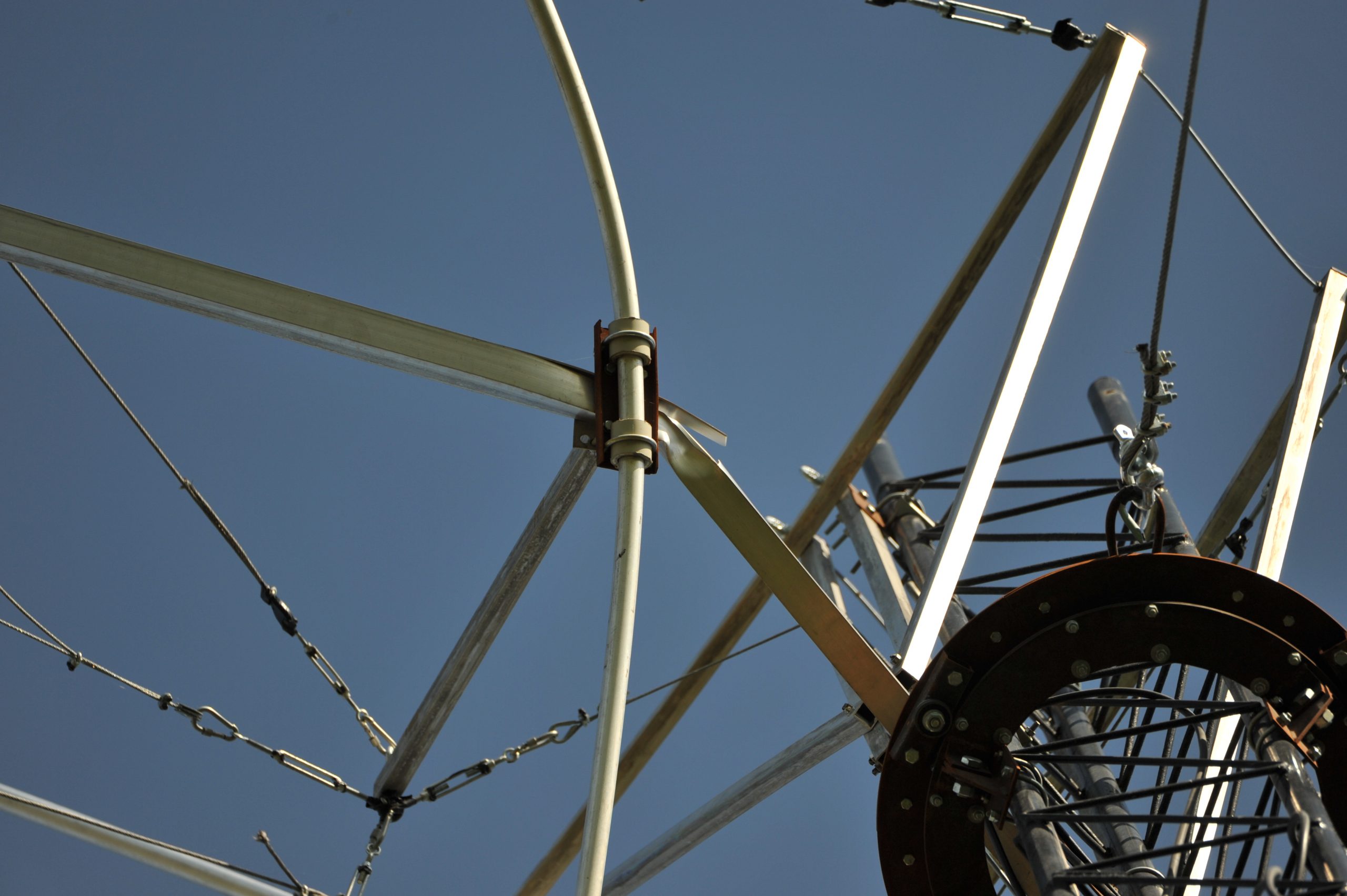
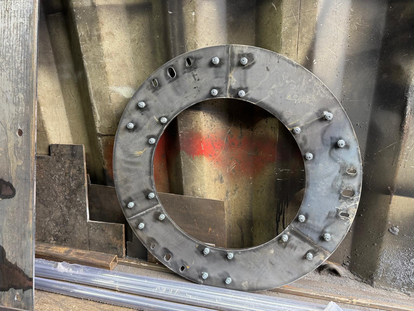
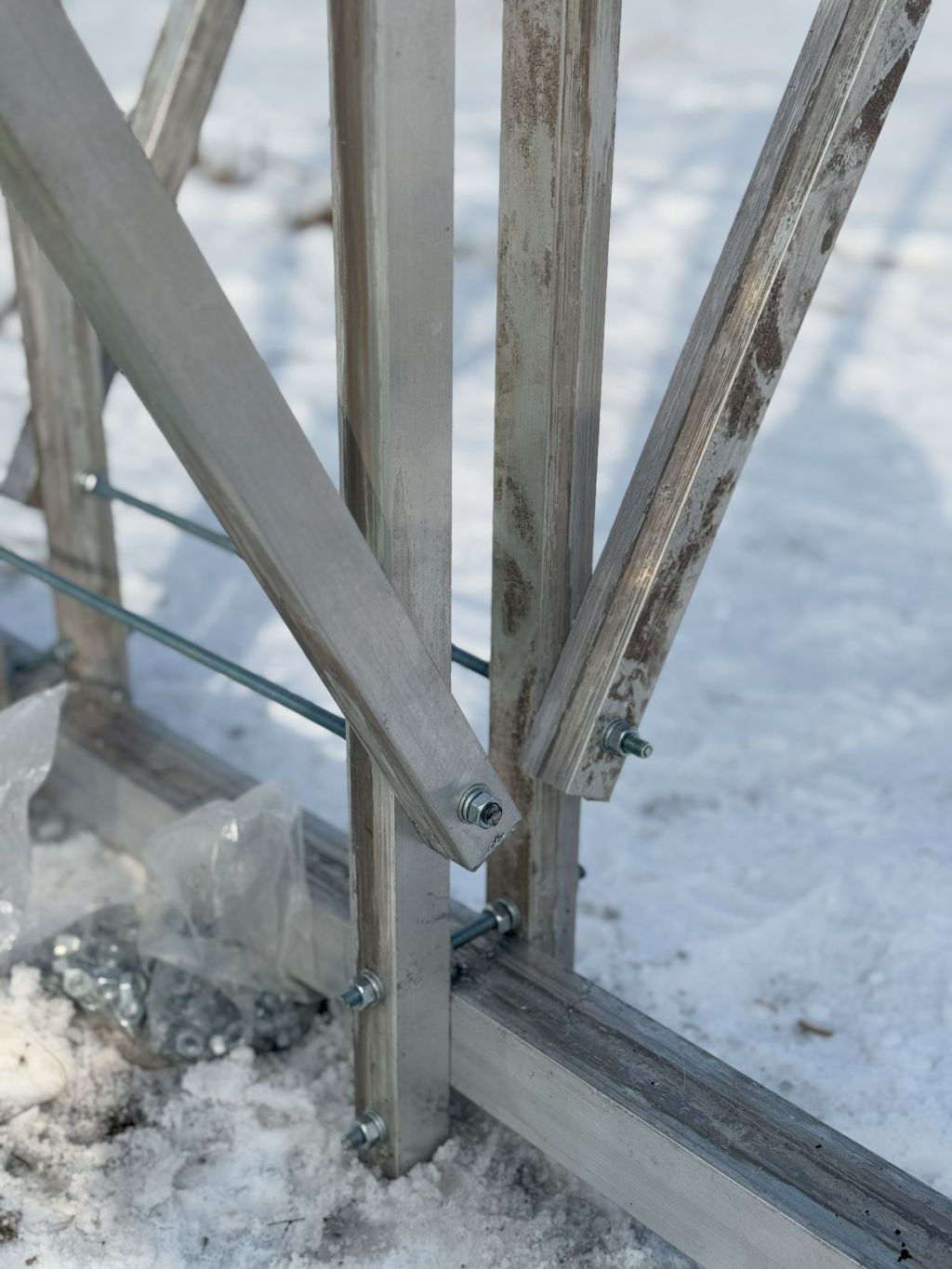
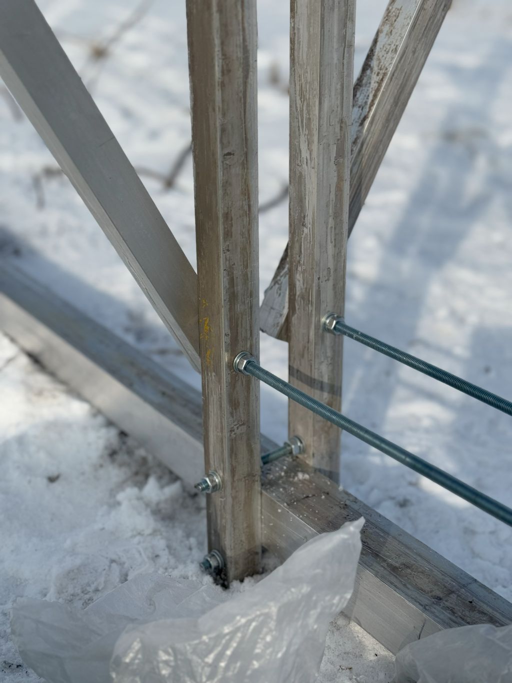
Risk of stuck orbital bearings
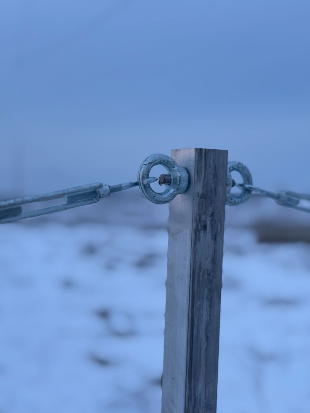
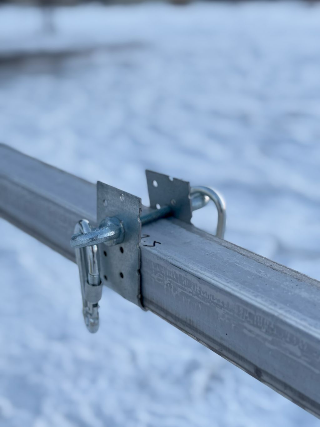
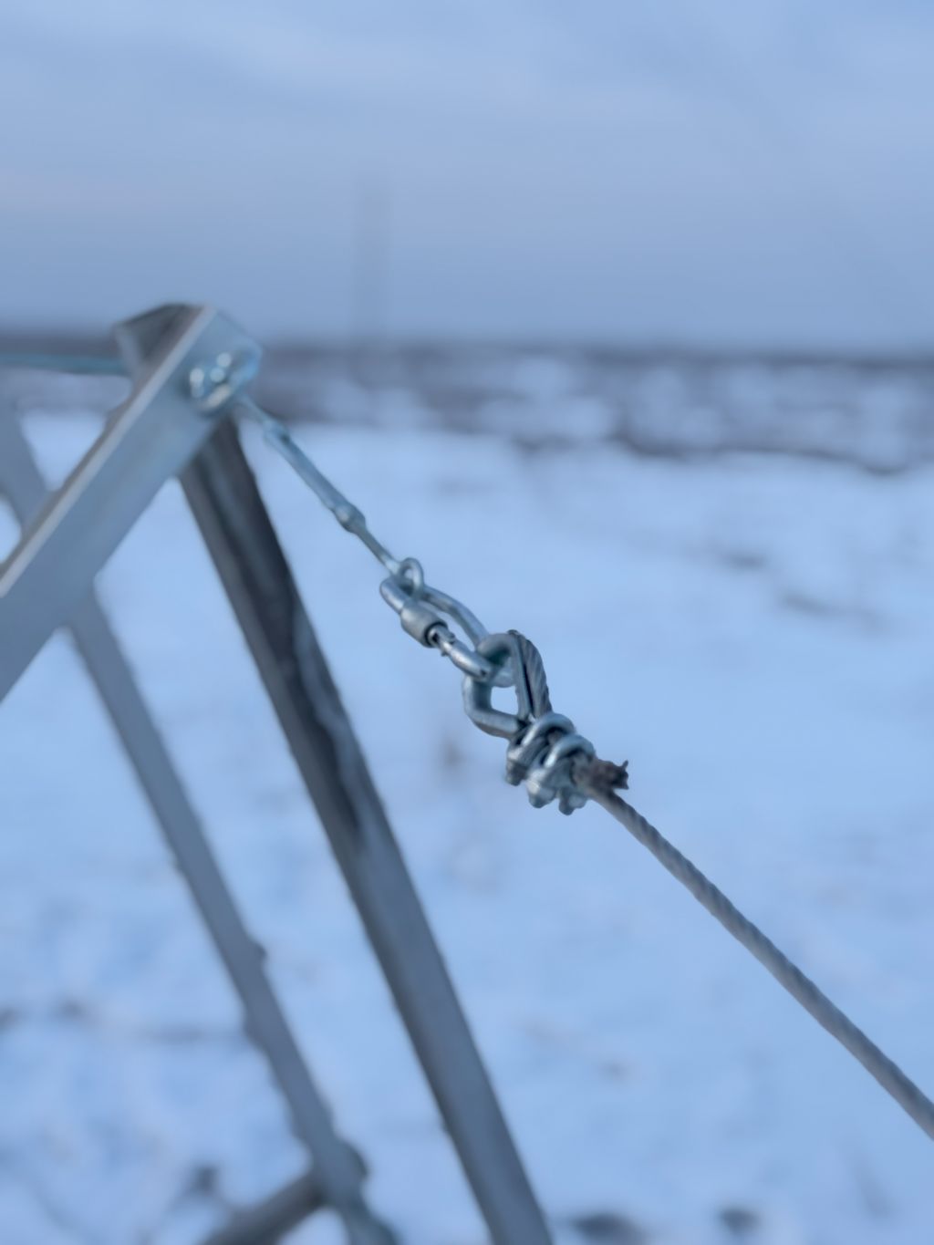
The second major risk was that the orbital bearings would be stuck because the assembly tolerances were much poorer than I expected. We had to adjust and check, check, and adjust. But still, the probability that one or more bearings would be stuck was very high and very real.
We pulled and shaken the guys before making them fixed to check that the bearings were rotating. They were doing well, which was a relief.
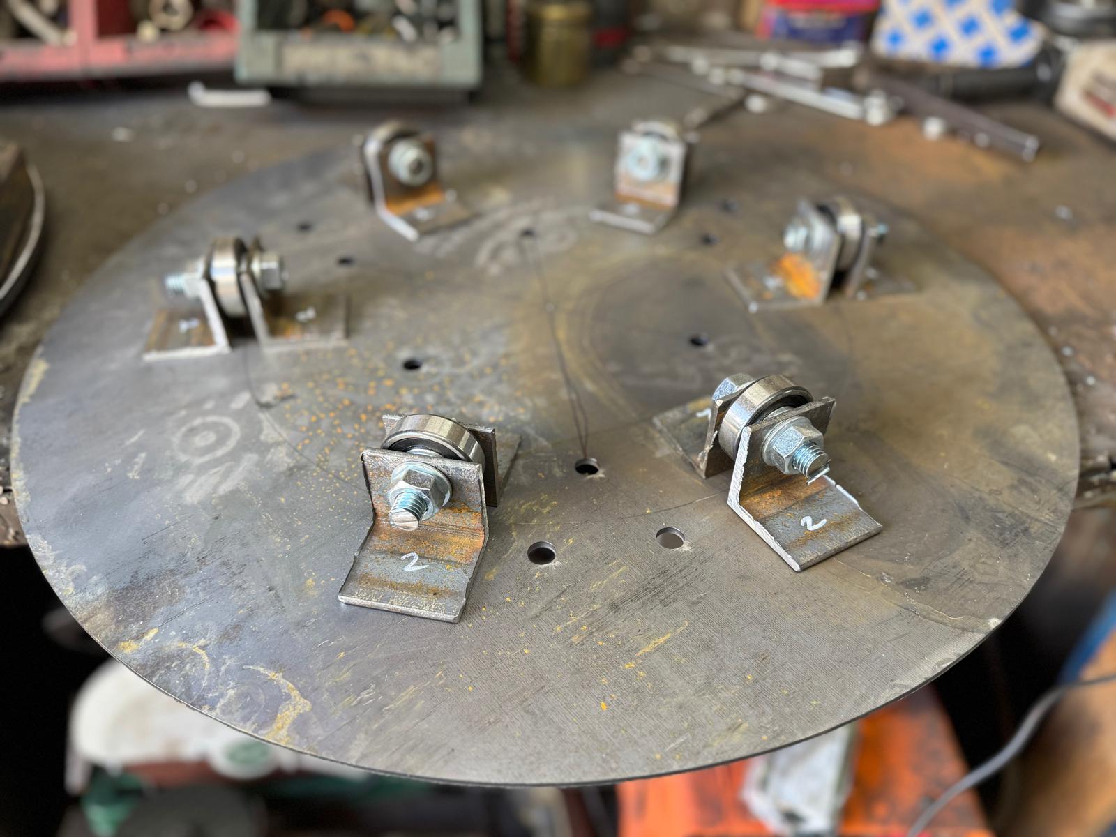
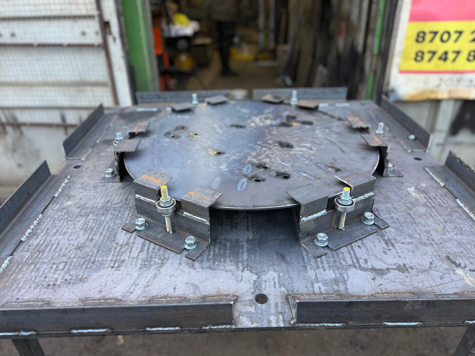
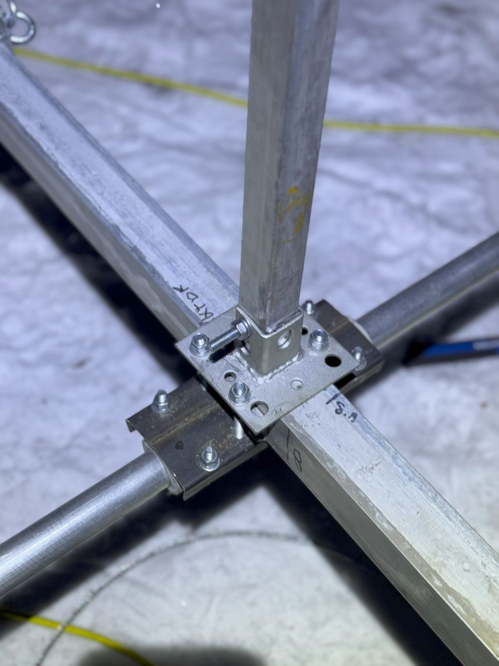
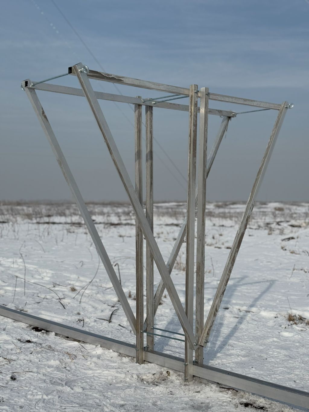
Risks related to the rotating table
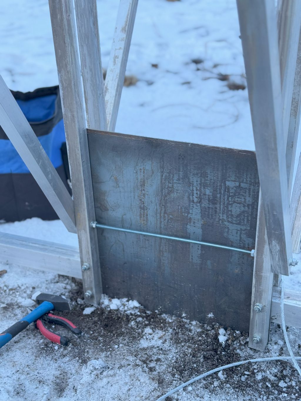
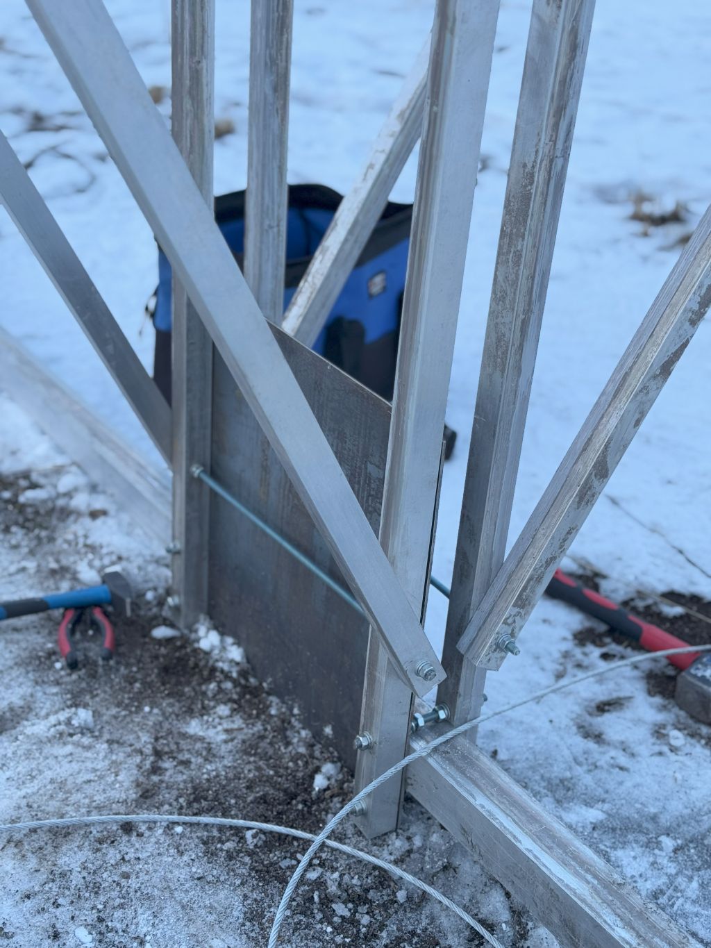
The rotating table could have too high resistance in bearings to support the tower’s weight due to the very basic – too soft steel – (and rusty) materials used and tolerances that are too high in every welding and cutting operation. Everything (except for the laser cutting) was too primitive but that was the only I could find with a reasonable budget.
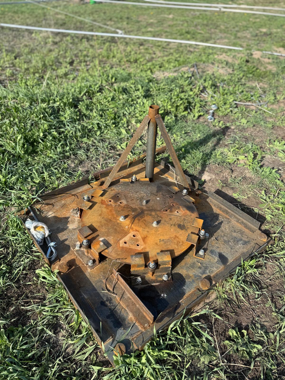
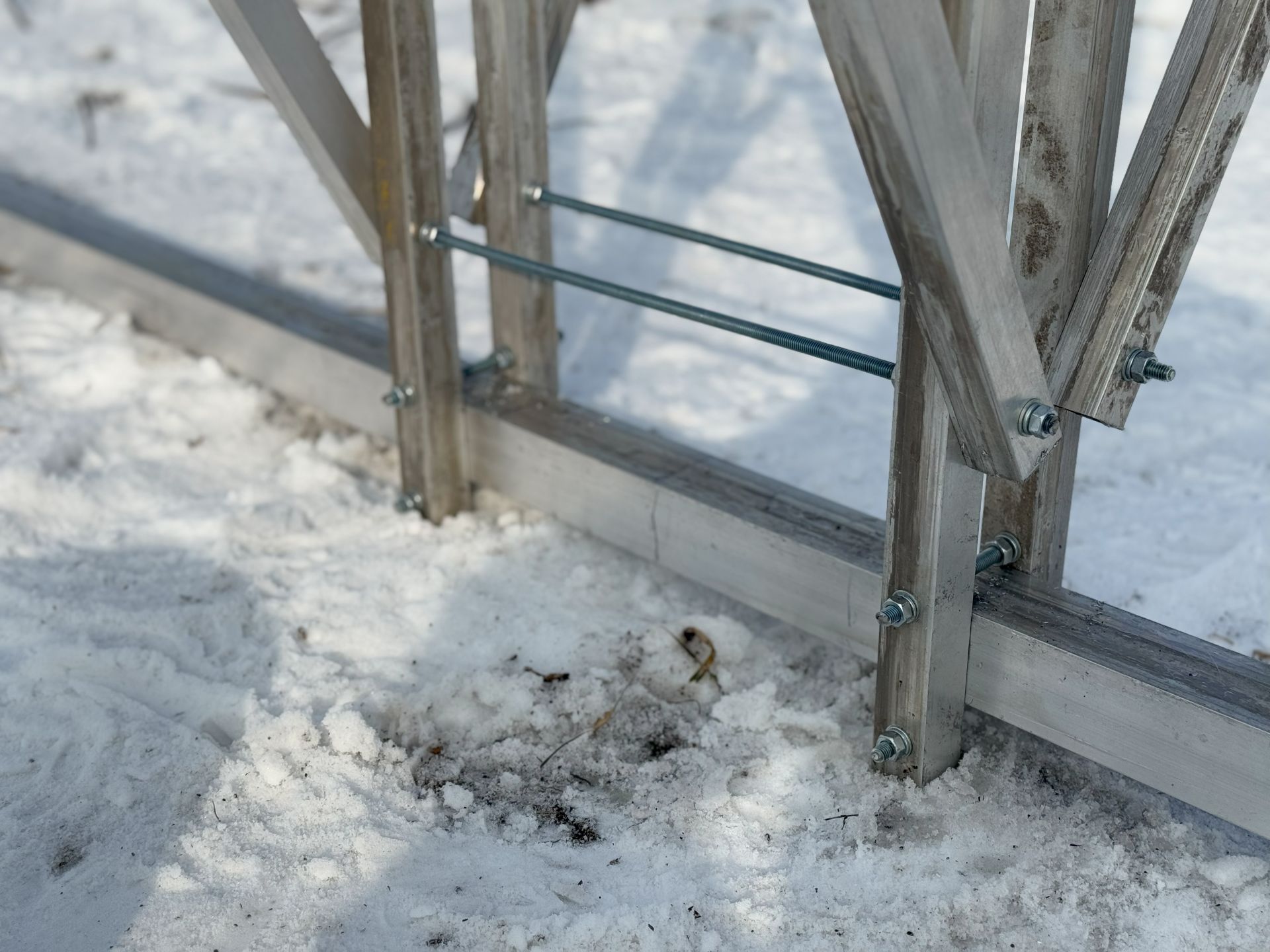
Since this is not my property, I couldn’t put 2-3 m3 of concrete in the ground for a solid and heavy foundation.
Even more! The table was installed on a frozen field in an area that looked reasonably flat in the middle of Kazakhstan winter. We had to dig 30 cm of snow to see the surface. So, it is not your nice, warm, clean concrete flat area with thick steel sticking out of it that you would expect for a tower of this size … 🙂
Instead of concrete, eight 1.5-meter-long thick nails are used at different angles. But for a mast of this size, if it decides to bend during the installation or later, it is absolutely nothing. Thus, the table can withstand a high left-right shifting load but very little pulling-out load. If the guys press the mast down and everything is OK, the mast shall be OK. But if something goes wrong, it can go wrong quickly and badly. Hopefully, it will not 🙂
Antenna-related risks
There were multiple risks related to antenna itself:
- Accidentally broken by people or equipment
- Too strong wind
- Broken during the accending
- The antenna is stuck with the crane due to there being too many supporting wires in the antenna. It is a true mesh of dozens of steel and Kevlar lines
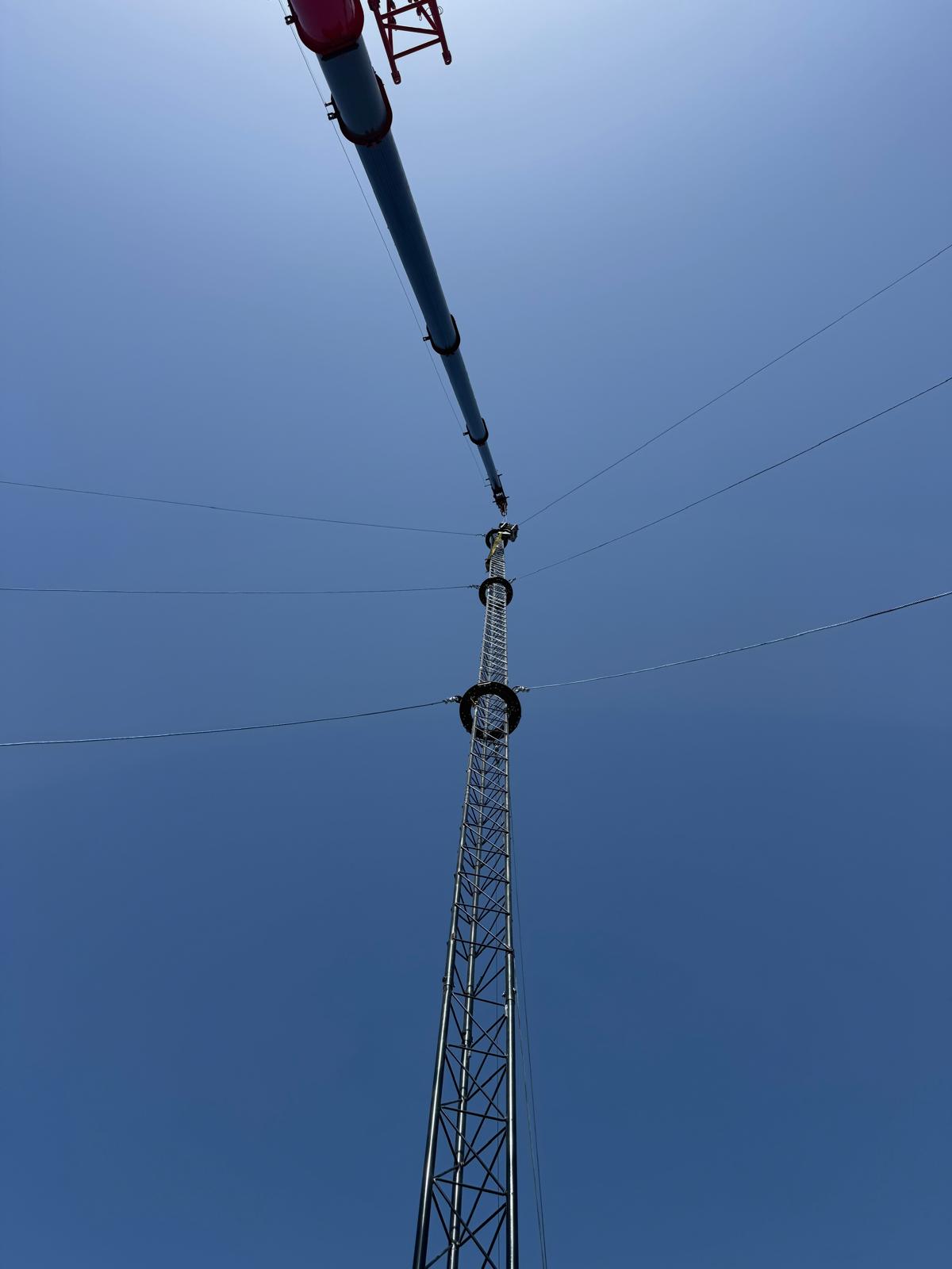
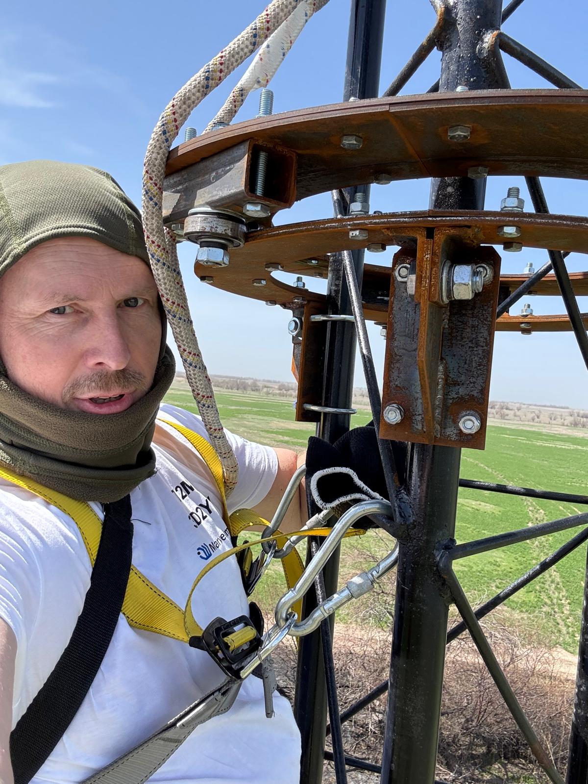
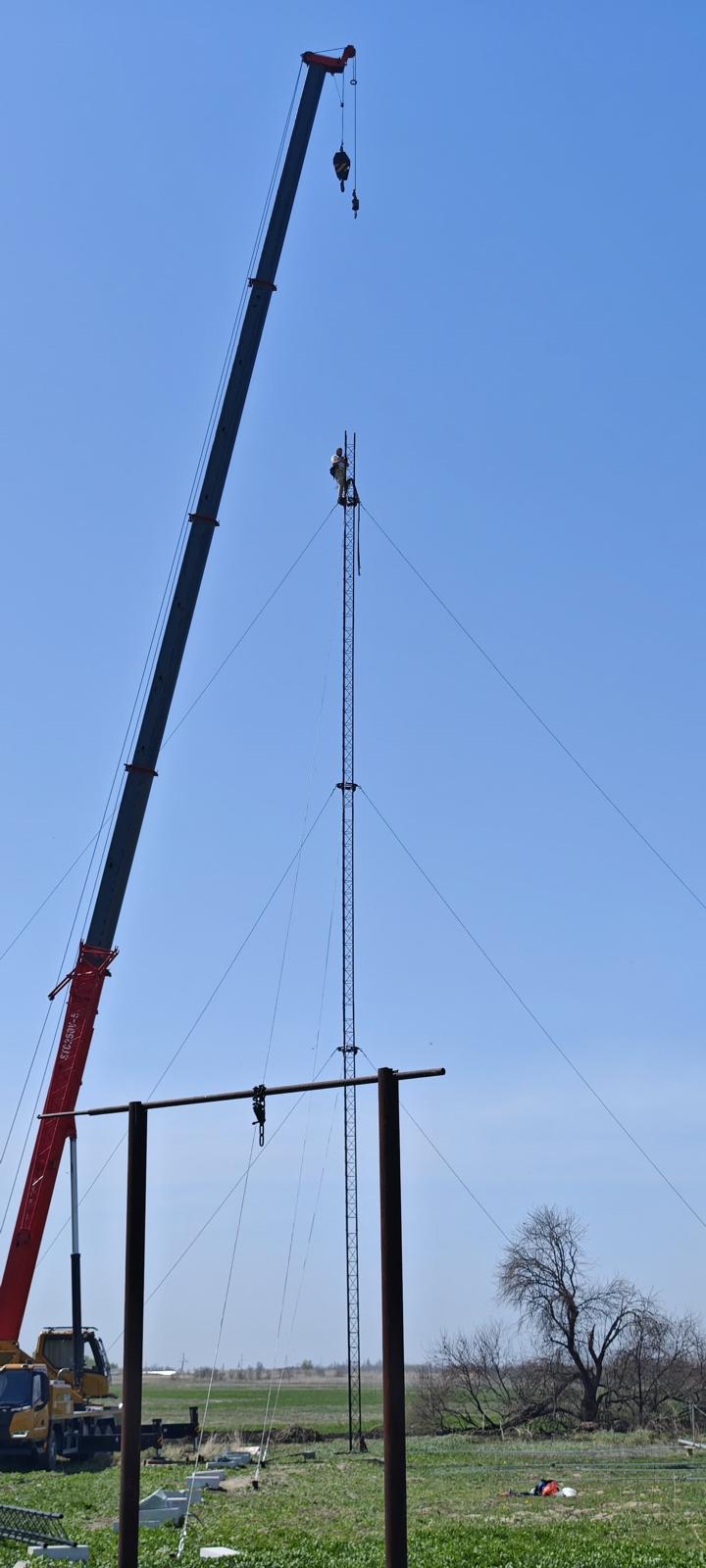
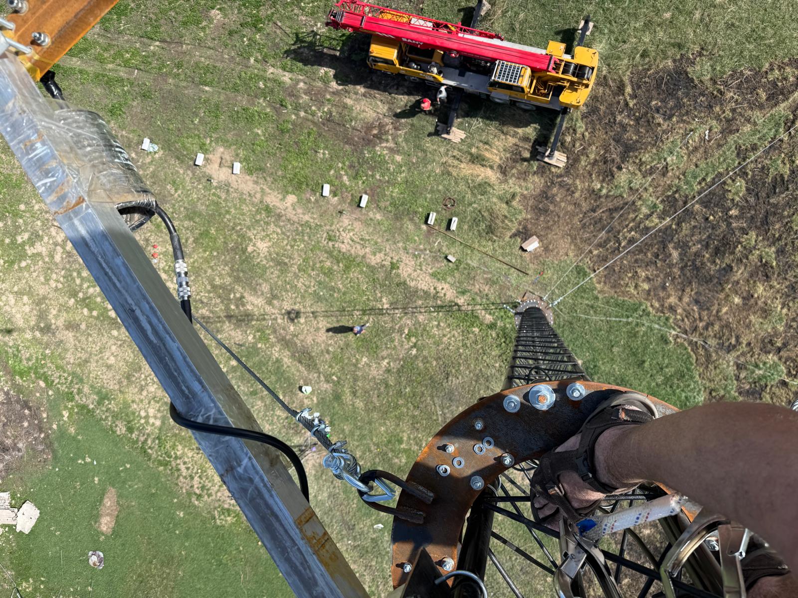
Unproven mast, unproven design, high height
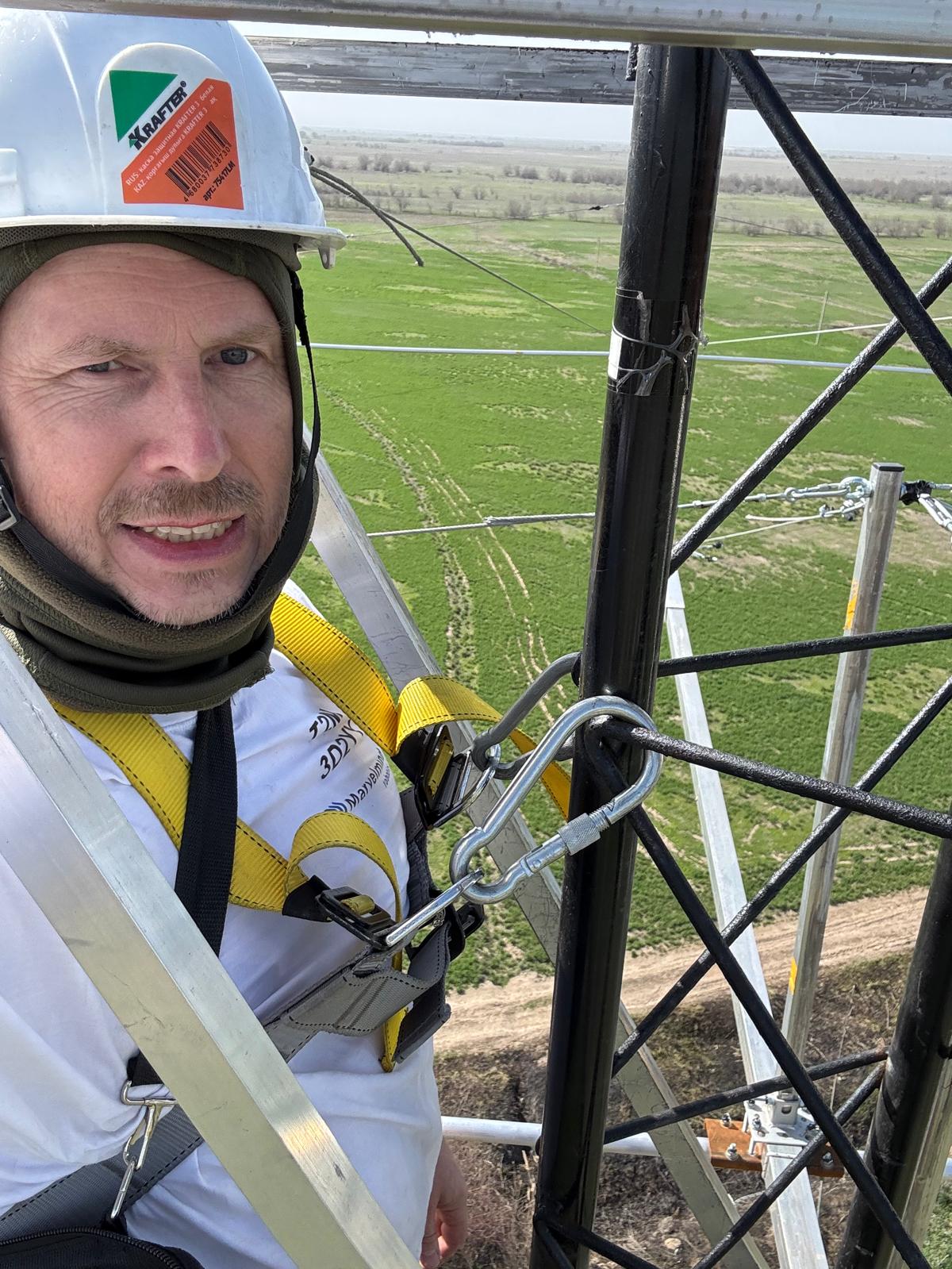
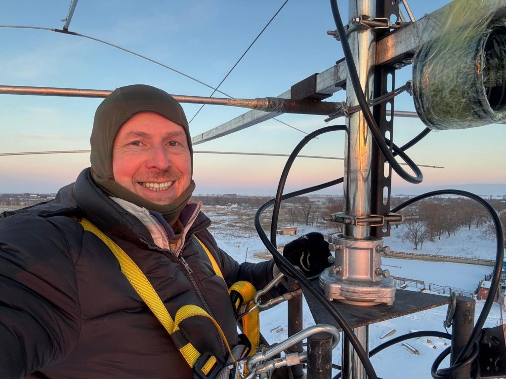
Tower climbing is risky in general, but climbing a rotating tower with an unproven design is particularly so. Everything looked reasonably solid. But things may change exceptionally quickly, and you can’t do much in a fraction of a second, especially when you are attached to a mast at a 30-meter height.
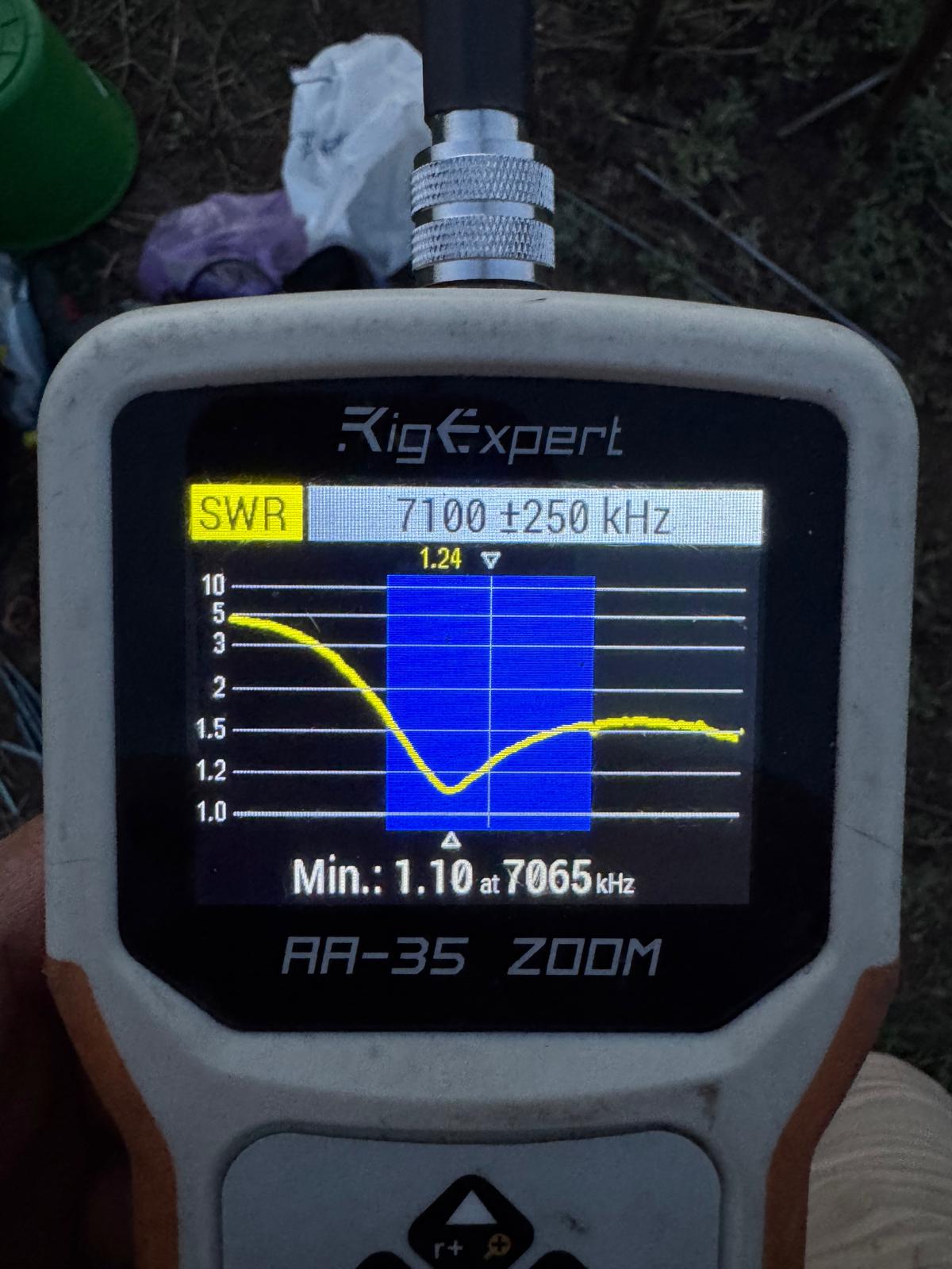
OWA Yagi and SWR shift due to changed ground
The OWA Yagi design is very flexible regarding SWR and is strongly recommended.
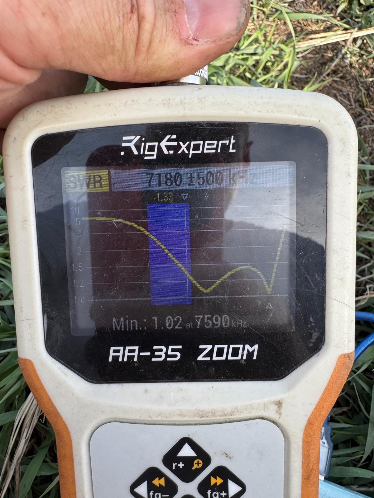
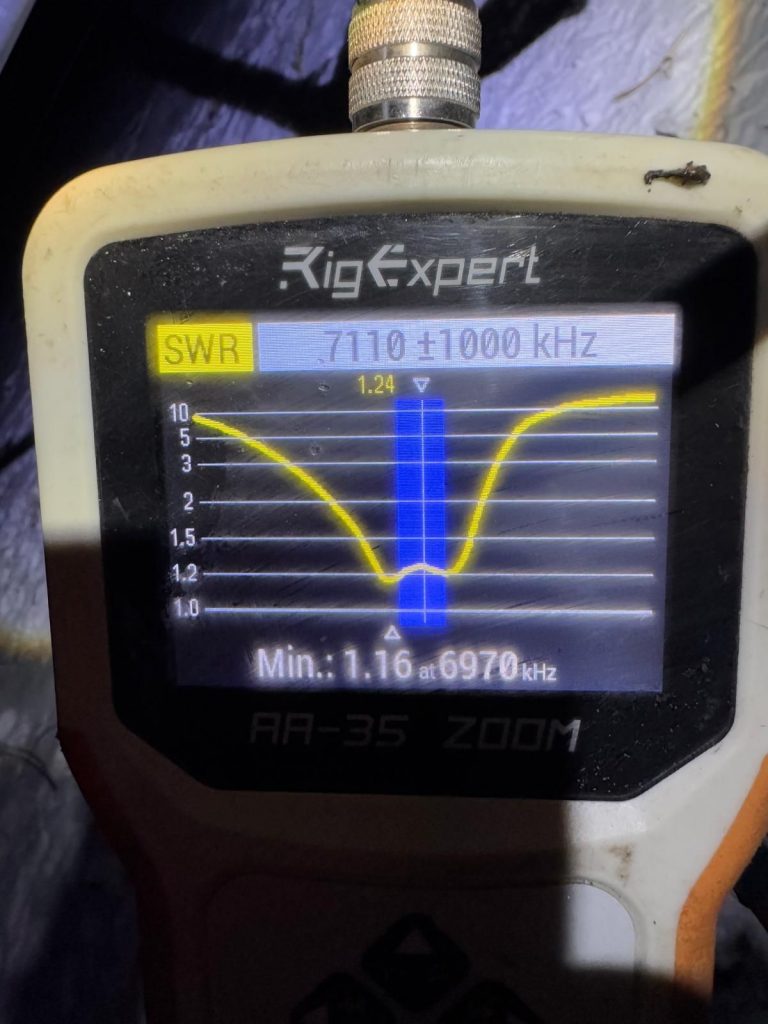
However, my design was too simplistic, and I had missed the central frequency. I didn’t have the time or energy to tune the antenna, so I shifted elements against each other and only tuned their length. As a result, I couldn’t shift the upper resonance lower. It remained too high. I successfully shifted the lower resonance, though. However, I saw two too-distant resonances, which indicated some wrong dimensions and, presumably, too high a coupling between the resonators.
Another mistake I made was underestimating the Earth’s impact. I am not used to lower frequencies like 7 MHz. As a result, the well-tuned antenna 4 meters above the ground had a much higher resonance frequency when it was lifted to the final height.
As a result, I will comfortably operate only on the upper part of the band 🙂
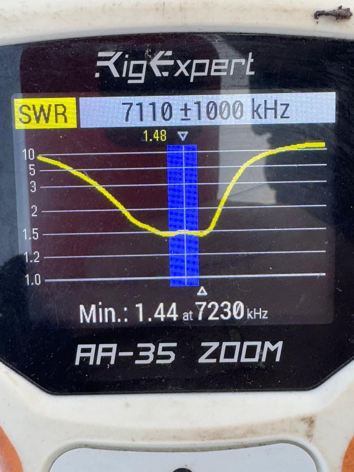
SWR: antenna is 4 meters above the ground; 5-meter cable
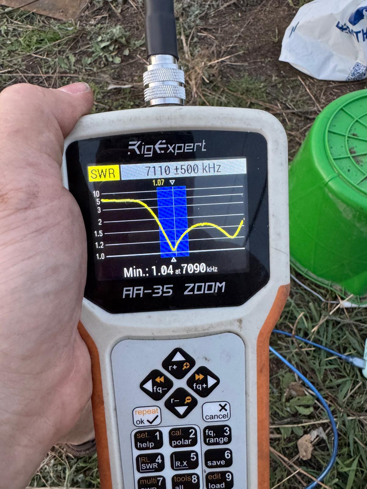
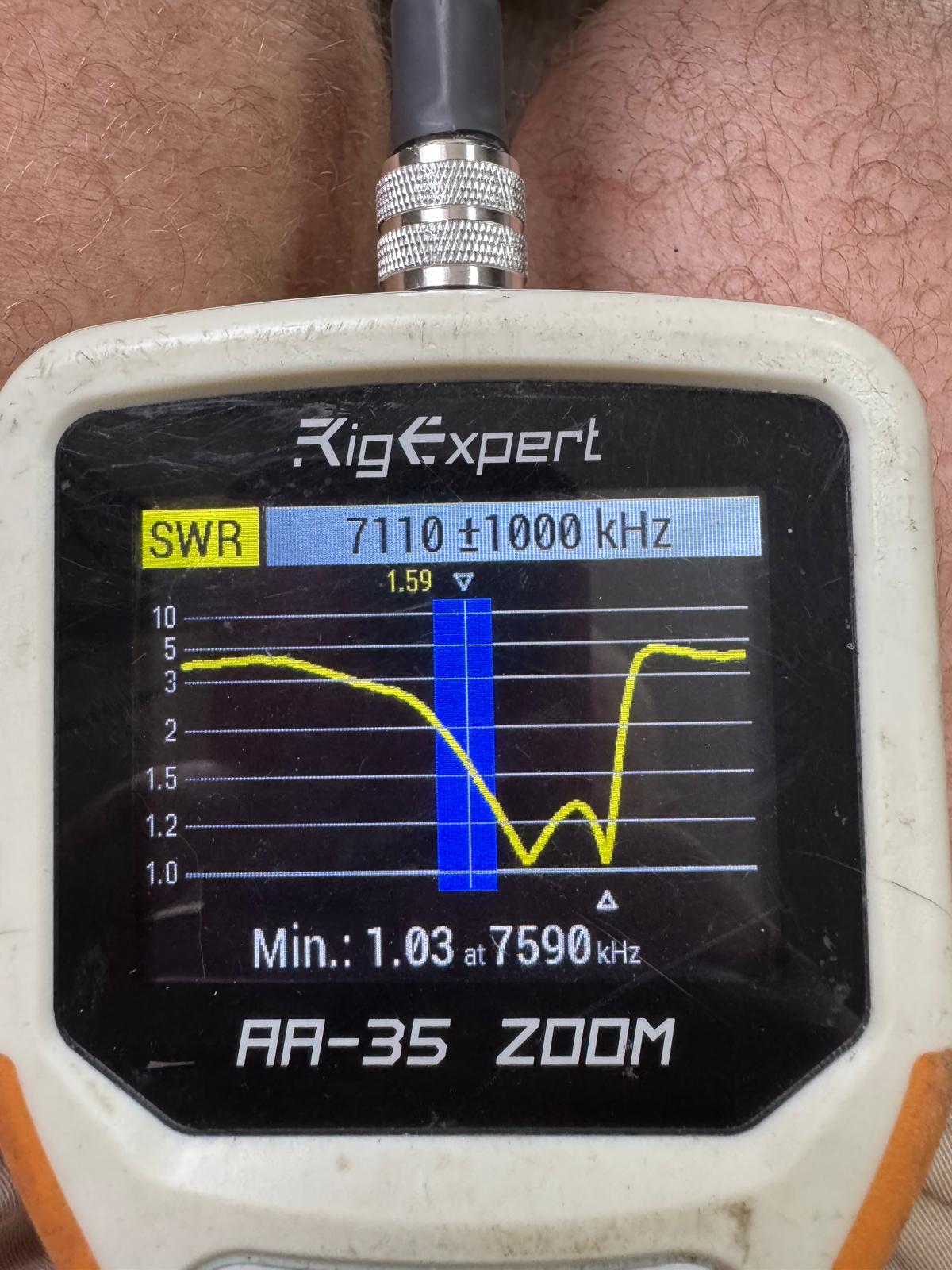
SWR: antenna is 30 meters above the ground; 35-meter cable
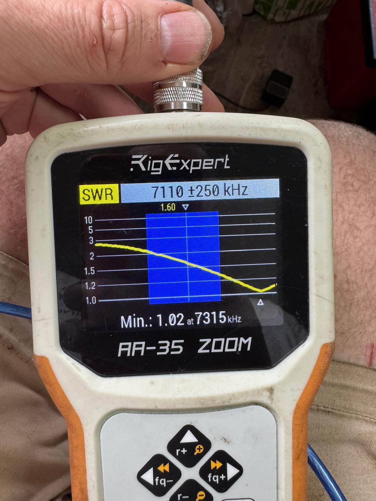
SWR: antenna is 30 meters above the ground; near transceiver - 80-meter cable
Well, if I have to call for a crane again – and it is likely that I will call for a crane because there are quite a few antennas that I want to put on the tower – I will need a few hours to tune the antenna more properly 🙂
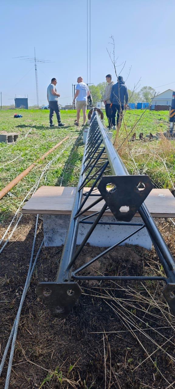
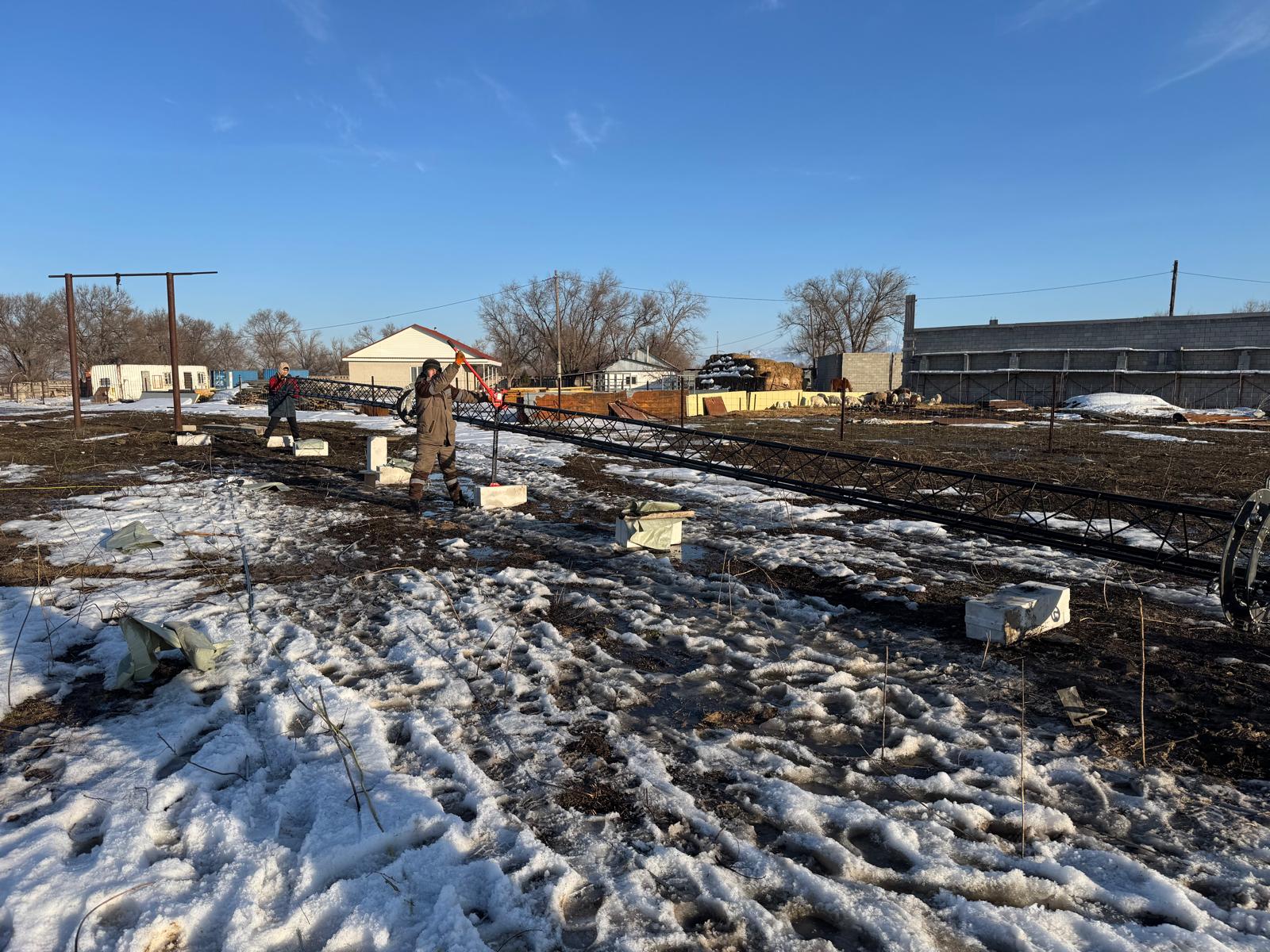
2025.Apr.12
We have celebrated Cosmonautics Day – the day when Yuri Gagarin went to space – by actively preparing for the tower erection that was supposed to happen tomorrow – on April 13th. Many small but crucial activities:
- Put down the lowest section and attach it to the main mast
- Remove the top section so that the total height of the tower becomes 30 meters – not 42 meters. It was very windy recently, and it is better to have a vertical 30-meter tower than a horizontal 42-meter tower with smashed antennas. I wanted to play super-safe
- Attached all guys
- Check one more time for other connectors, etc.
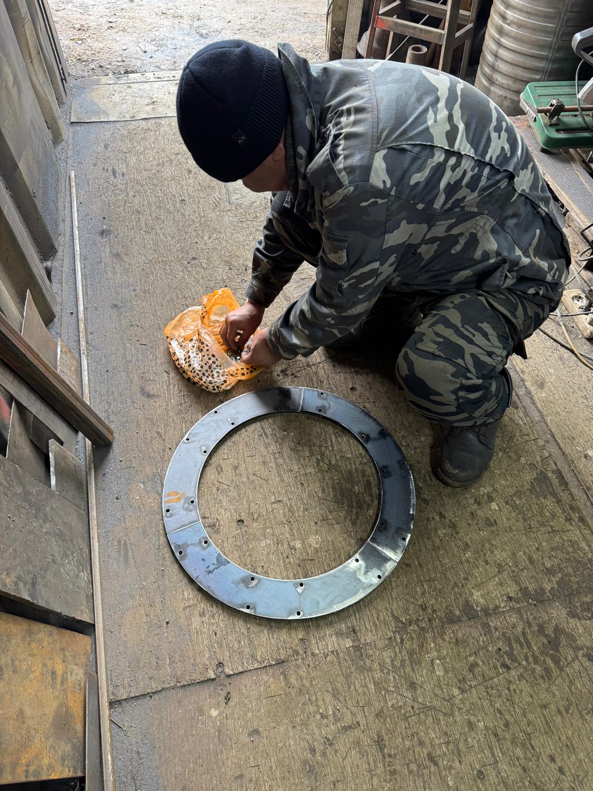
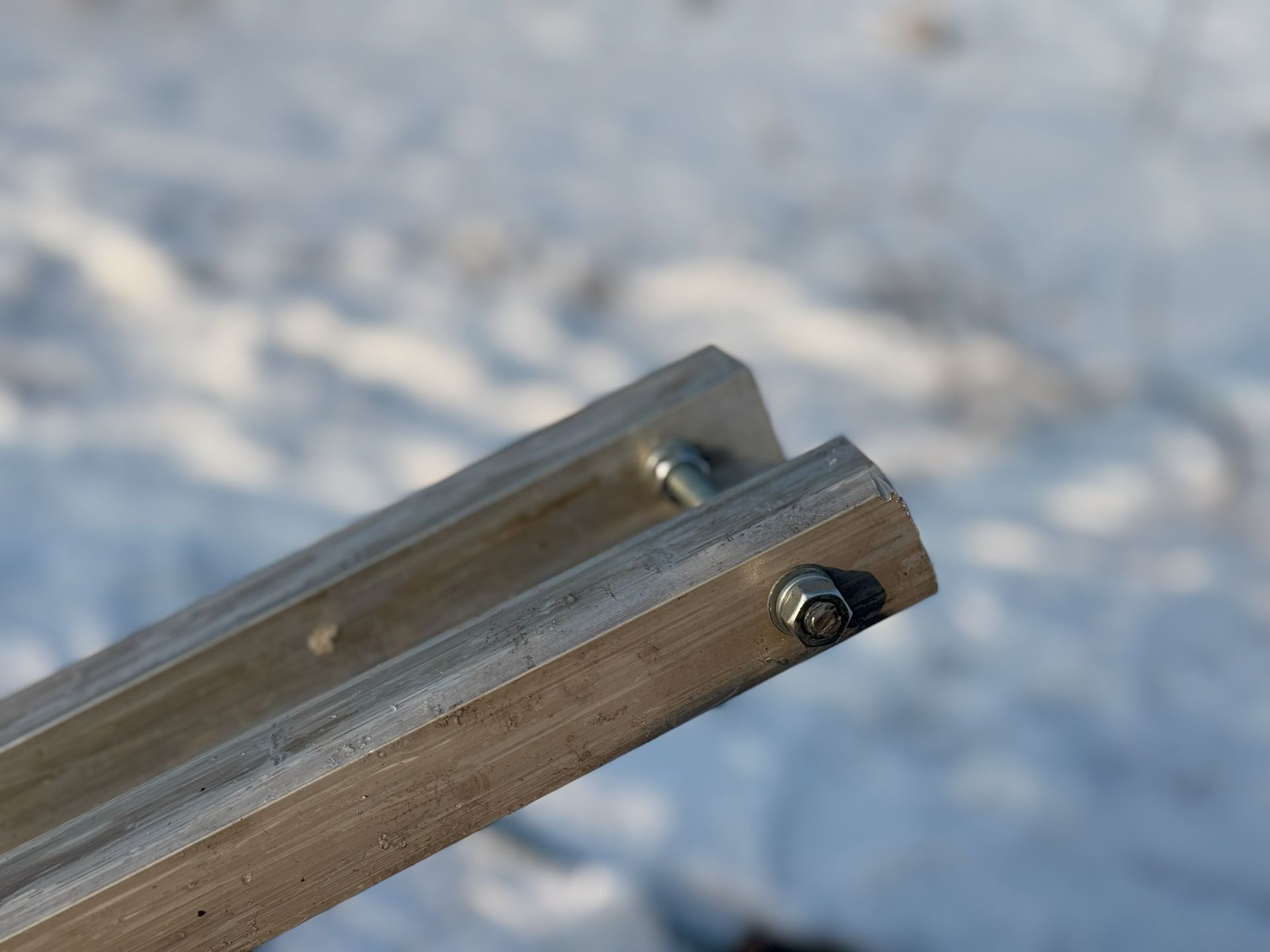
- Put compound on all screws on the antenna – to try to minimize chances of self-unscrewing under vibration that I see all the time
- SWR tuning and measuring final element sizes
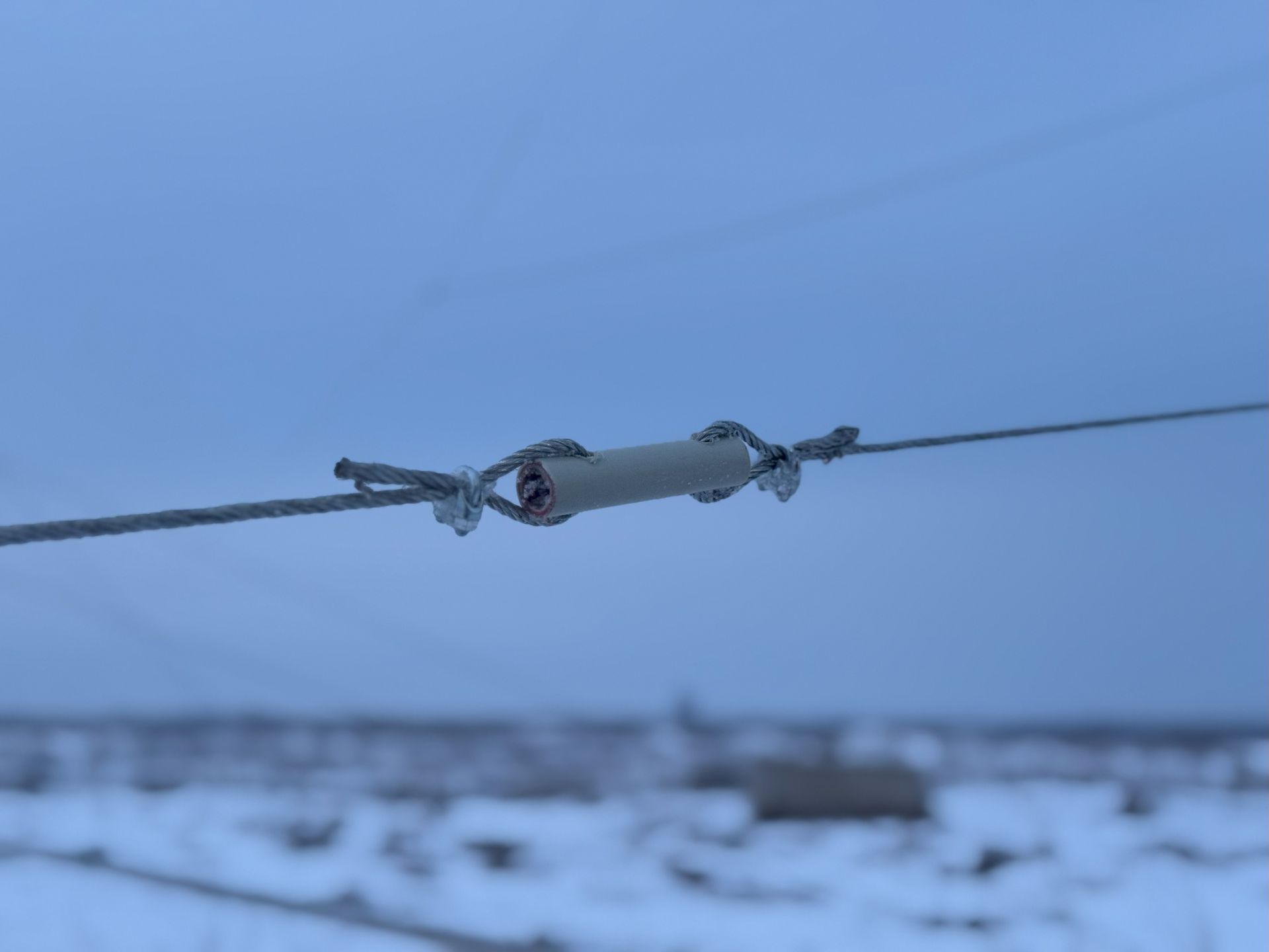
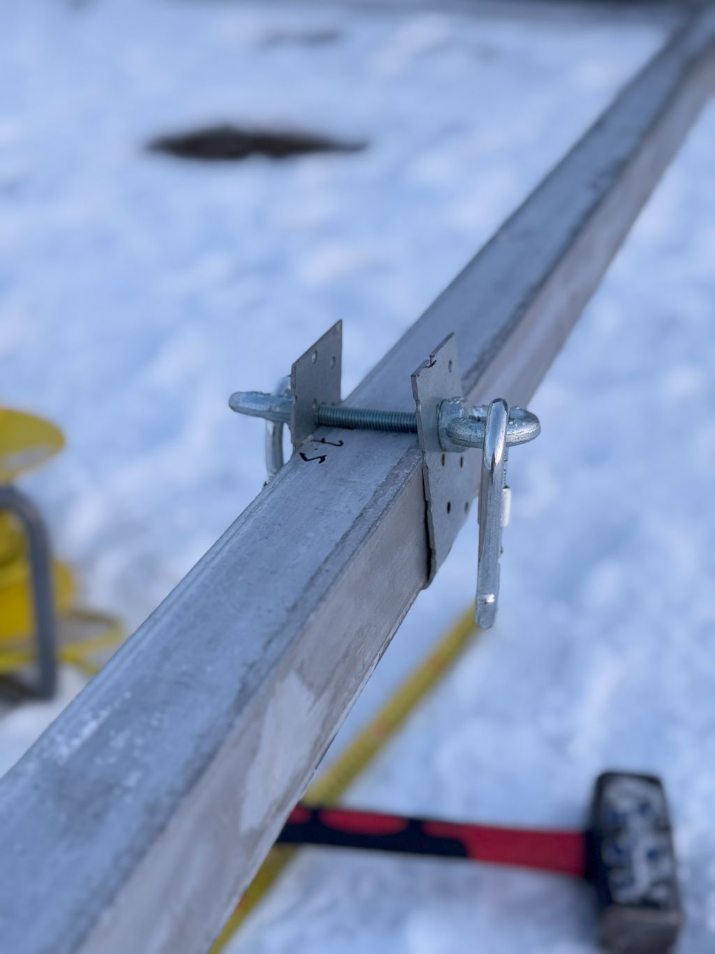
- I put Kevlar lines (1.5-3mm) between all elements so that they would hold the elements in the wind
So, a lot of essential steps to maximize chances to succeed on the next morning when the crane comes.
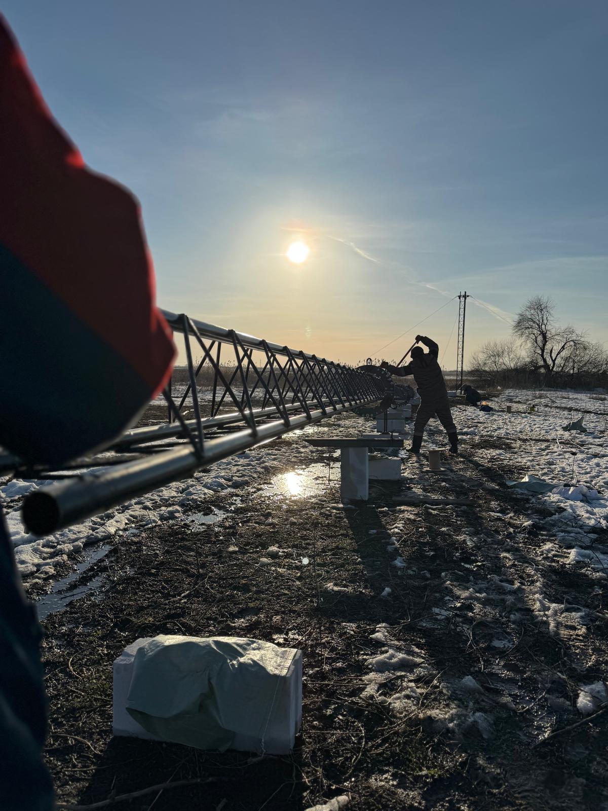
2025.Apr.11
Many things have happened since the last record (again 🙂
- See 2025.Apr.11 notes in the Remote QTH blog to learn about the lost Yagi for 20-meter and 15-meter and the crushed mast. Sad 🙂
- Tomorrow, we will prepare everything for the big Sunday. This Sunday, we will try erecting the tower… first, the 30-meter version. If it works, we will attempt the 42-meter variant. So many things may go wrong! But we will hope for the best and pray for all supportings gods 🙂
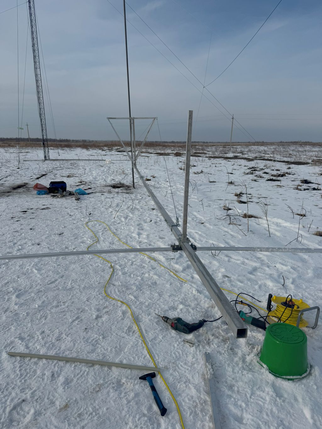
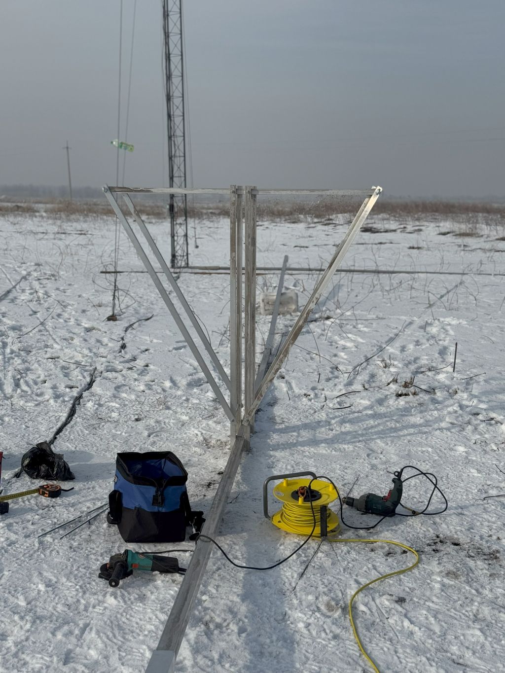
The 40-meter 4-ele Yagi finally takes off the ground for final tuning. It is installed on a temporary mast section about 4 meters above the ground.
Though the antenna was presumably assembled nearly two months ago, I spent several days making it more rigid:
- Multiple supporting wires between different elements
- Kevlar threads of 1.5-3mm to keep the elements from swinging too much
There was a powerful storm in Almaty just a few days ago. Such a strong wind sends a clear message that it is better to have a standing antenna 30 meters above the ground than a fallen antenna on the horizontally positioned 42-meter mast 🙂
Again, no guarantee that the 30-meter mast won’t fall, but somehow, the 30-meter option looks more realistic and appealing … 🙂
Maybe the stack of antennas will look like this … if we raise it at all 🙂
I again spent several days trying to find a crane. I contacted 20-30 potential subcontractors, but prices were insane, or the cranes were unavailable. Eventually, I found a couple of options for 500 USD/day, which was about two times higher than my mental limits for this job. However, there were “local peculiarities” forming the price. The transport police collect about 200 USD per permit. Thus, moving the crane between the sites is costly, and a one-day job is particularly costly per hour/day. But I couldn’t find anything better after more than a month of trying.
I seem to miss the optimal dimensions, after all. OWA works beautifully and gives the freedom to tune the SWR. However, my design and approximation were too rough. I didn’t have time to set up the simulation. Perhaps it is a significant mistake. But I want to move on with the tower. If it doesn’t fall, I will be delighted with this antenna as long as it stays there as long as possible. I won’t change it now. Maybe, in the future
2025.Feb.24
Many things have happened since the last record:
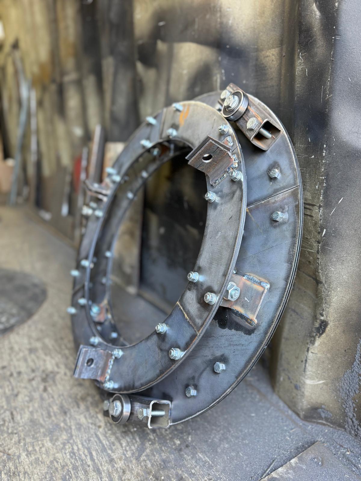
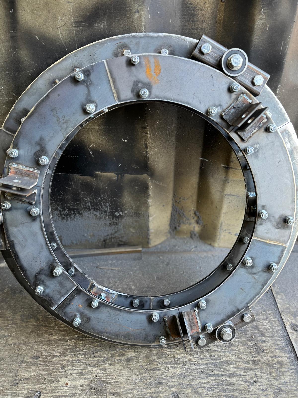
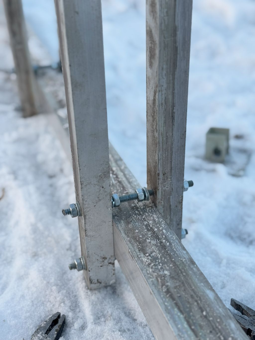
- Three more orbital bearings were made. Despite spending additional 1/2 day with the welding guy and despite he made the first orbital bearing and despite he had all required blueprints, he messed up dramatically with the bearing:
- The supporting bearings are welded on the top side of the lower part of the bearing instead of the lower side of the upper part
- Alignment and welding tolerances of 0.5-1 mm are not met by far. Instead, there are errors and gaps up to 3-5 mm
- He delayed the job by two days, made it of low quality, and asked for that more money … “I worked so much”. Damn it. You didn’t work much! You reworked your failures. And I had to spent an extra-day with him side by side. Otherwise, he wouldn’t even notice the mistake. Now, one bearing is of one type, and three other bearings are upside down partially … Bad
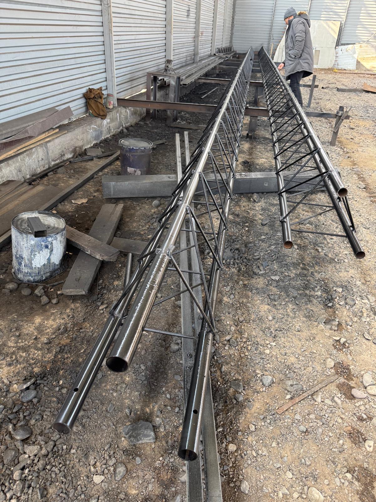
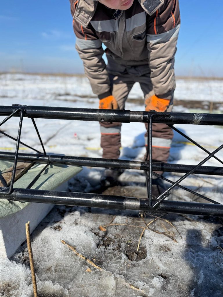
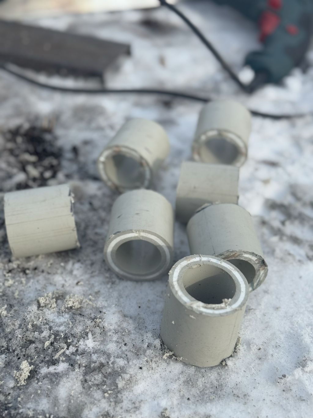
- Six more 6-meter sections were welded. Initially, they were planned to be connected by flanges. However, installing the orbital bearings without disassembling them made it impossible, which is a tough job. Thus, flanges were replaced with tubes of 40 cm in length and a larger diameter than the main tubes of the sections and welded to one section and presumably relatively loose on another side to be bolted to it. However, the tubes turned out to be too close in diameter to each other. It may be good for the rigidity of the whole structure, but one needs a heavy hammer to assemble and disassemble the sections. It automatically means it wouldn’t be possible to put section after section on the height. They must be assembled on the ground and lifted from a horizontal to a vertical position, which is a very high risk for such a long structure. It may simply break and ruin everything. This is one of the highest risks for the whole project as of now
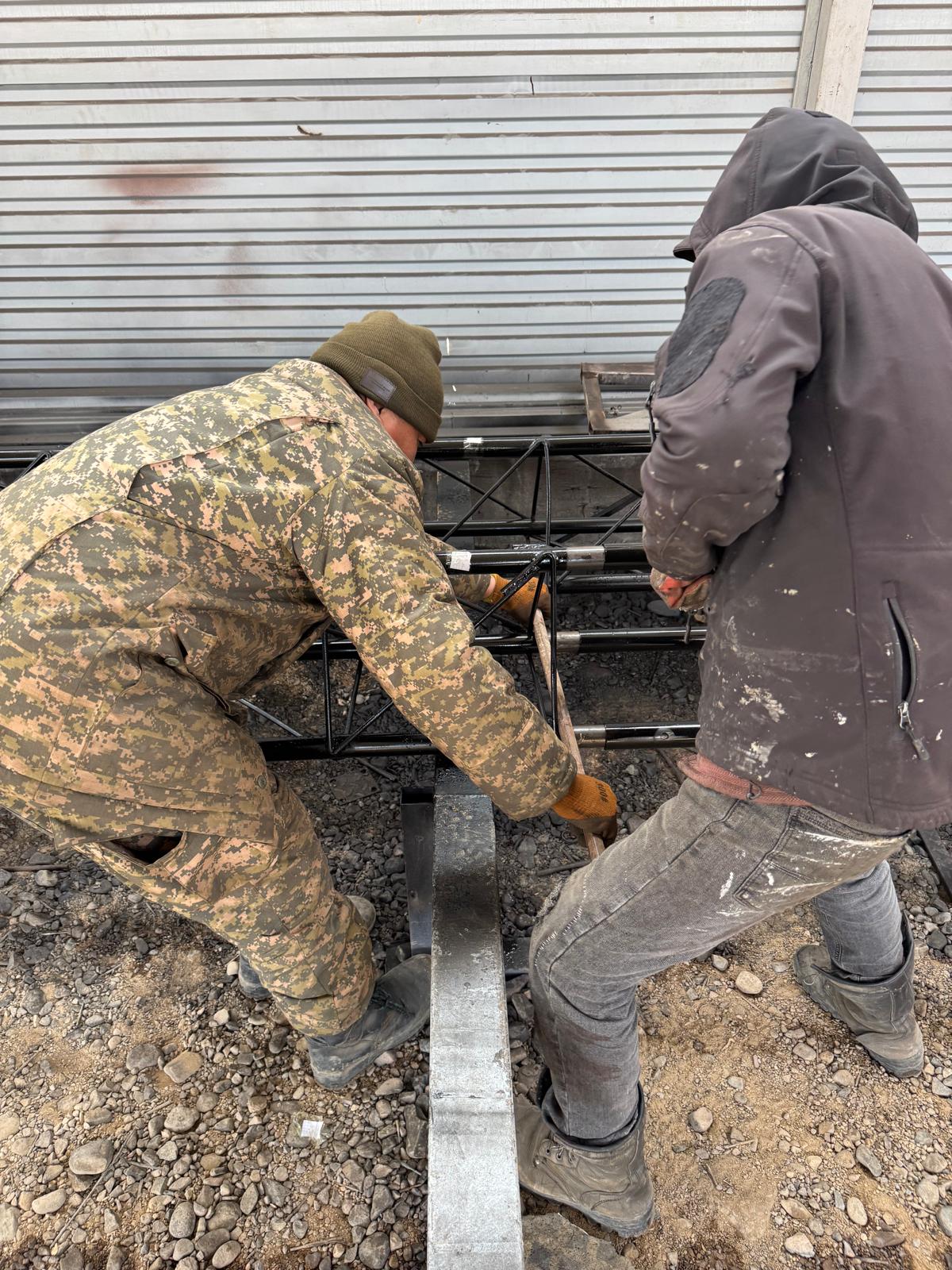
- A dramatic improvement in operations is that I found an online service, Naimi.kz (“hire.kz), and quickly hired a a couple guys to do the installations on site. It wouldn’t have been possible otherwise. In the past, when I tried to find similar help, I was quoted totally outrageous sums.
We spent the whole weekend with a team of two guys on the first day and a team of three guys on the second day:
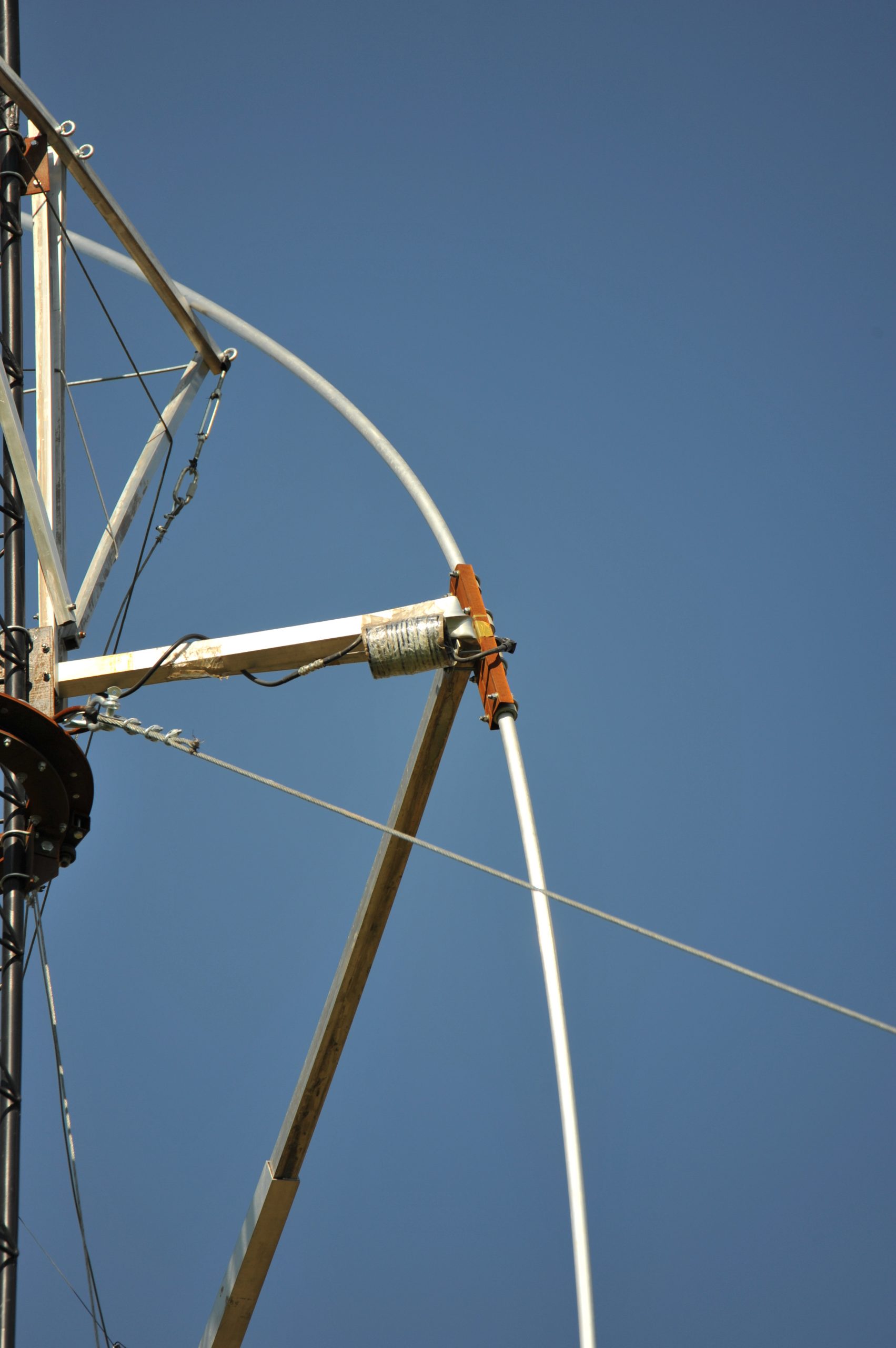
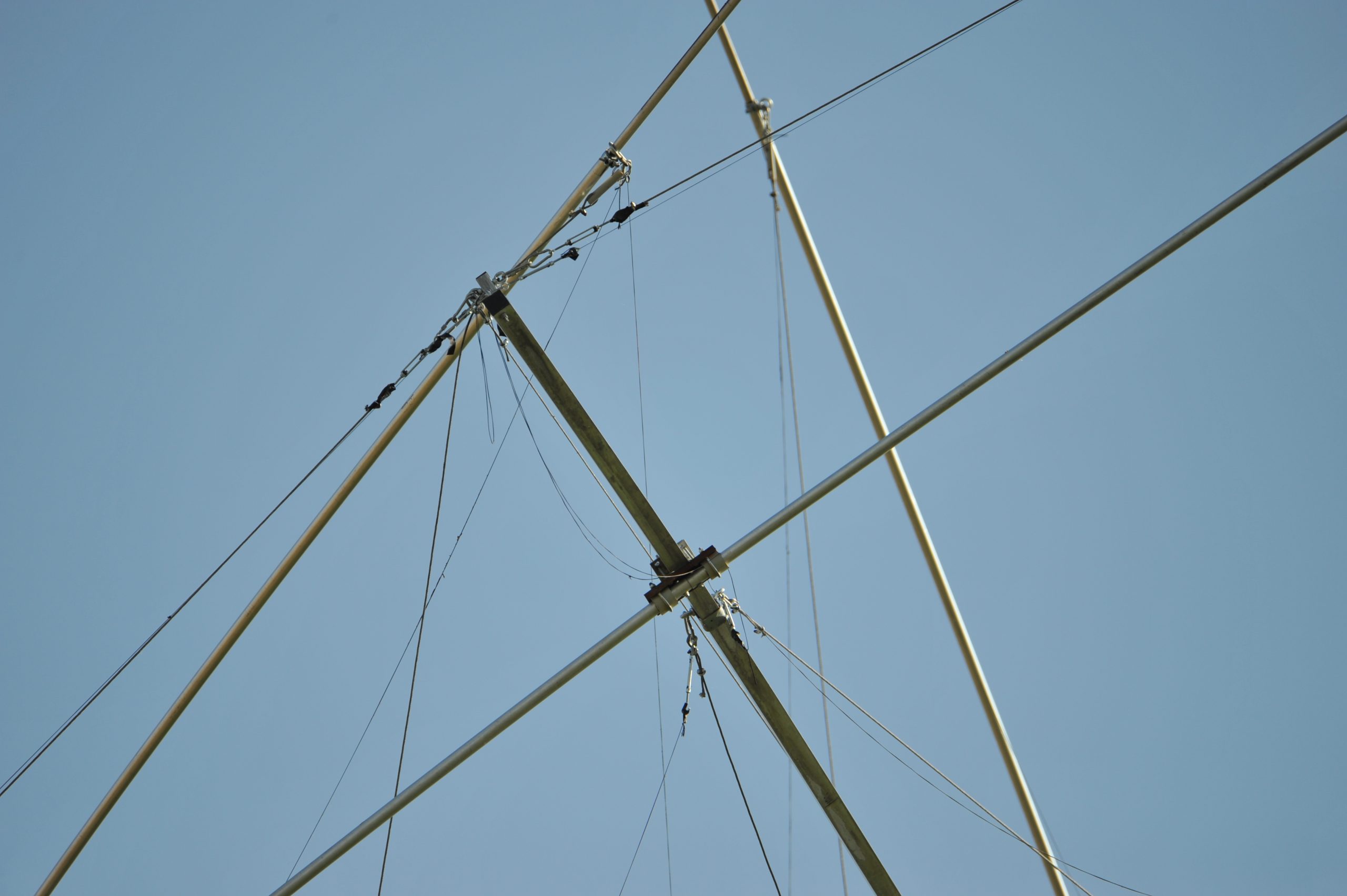
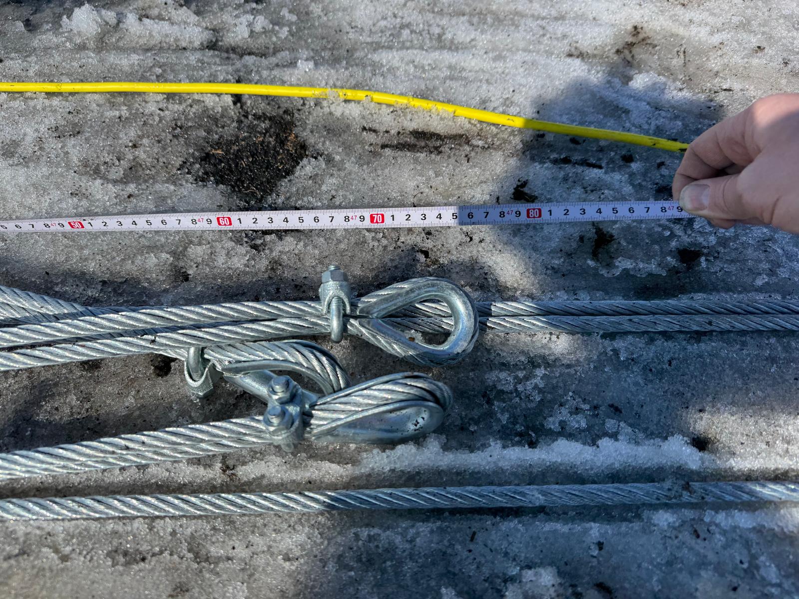
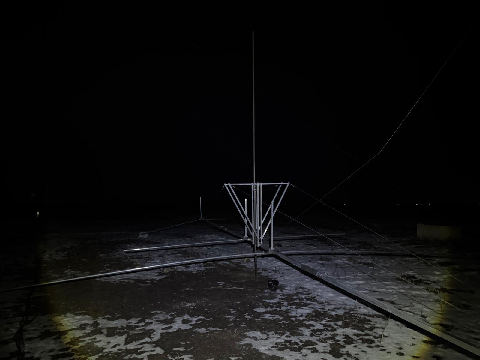
- Prepared 10-mm guys – 12 pcs: 4 layers with three guys in each layer. The antenna plan changed multiple times. Eventually, it started looking like this:
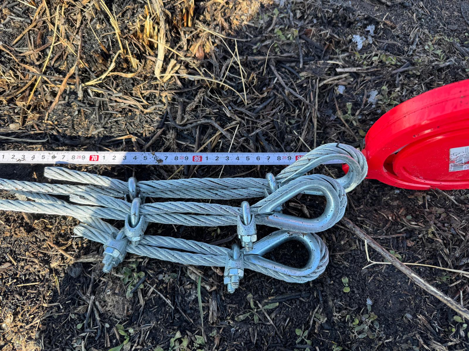
- Since the space is limited, the angle between the guys is not exactly 120 degrees, which adds to the risks
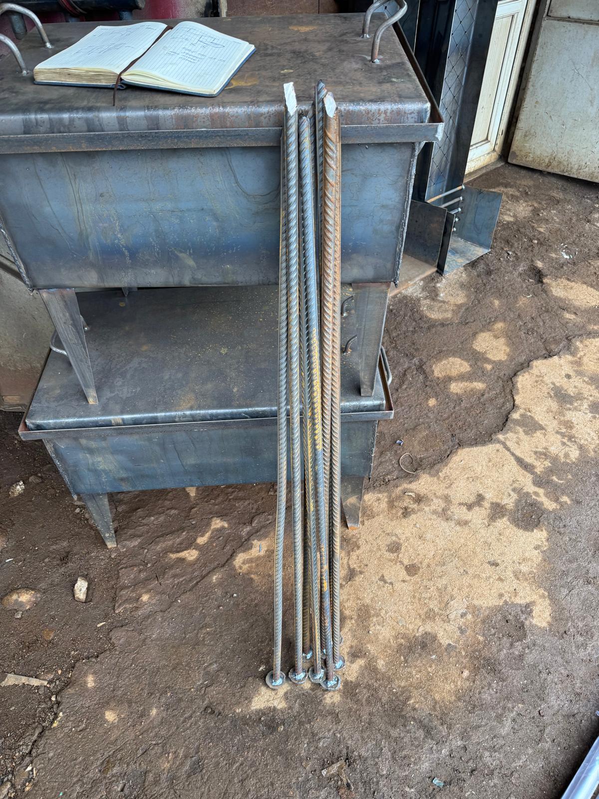
- Put 6 six more anchors to the ground. The first layer (11 meters from the mast) – 1200x50x50x4mm. Two more layers – 1500x75x75x5mm. Big guys put several tons of concrete to the ground. I am not sure why so much … the weakest point would be the guy anyway … However, the concrete is out of the question for me because it is a rented piece of land
- One of the pivotal experiments was to check whether the mast could be lifted with all sections assembled. I really want to believe in this and may bend the reality to the wish, but it looks like it can… but I am not sure 🙂
The bending test was done with five sections instead of 7 seven sections and without the fourth orbital bearing. The bearing is heavy and is placed in the middle of the seventh section. Maybe it will be the last straw … However, we had many other things to do. So, the test with five sections was successful. However, it has to be repeated with seven sections together when they are put down.
One of the significant open questions is how to put the antenna to the tower:
- Together with the top section. It is safer and easier with the crane. Perhaps
- Or, maybe it is worse because the section number seven with antennas must go to the very top, and combined with the crane height limitation and the large size of the antennas, it is a mission impossible
- Maybe it is better to install the tower first and then install the antenna when the tower is entirely secure and safe
- The approach with 6+1 sections would help minimize the mast bending because six sections are safer than seven sections to lift, with the top section having a bearing on it to make the situation even more difficult. However, a significant rework of the connecting part between sections six and seven would be required. Now, they are too close in diameter to combine easily. It is difficult to perform on the ground with the help of a large hammer and virtually impossible on the 36-meter height
- Maybe it is better to raise the antennas without the crane at all – but releasing one guy on the bottom, raising the antenna above the guy, securing the guy, securing the antenna on the mast, moving the winch upper, raising the antenna again, and repeating with releasing one of the guys. Most likely, releasing one guy out of twelve in perfect windless conditions is safe … but somehow, I don’t want that 🙂 Later, maybe, for smaller antennas below the 40-meter antenna, when the mast will prove solid and stable. But right now, it doesn’t look like a very appealing
I don’t have a clear view of what is the best, but somehow, I gravitate to an option when we raise the tower first—at least something will be secure and confirmed—and then solve the issue with the antenna. Combining together may be smarter, but it makes the operation too complex, and it is easy to make very stupid mistakes and ruin everything—totally everything. The height is significant. The weight is significant.
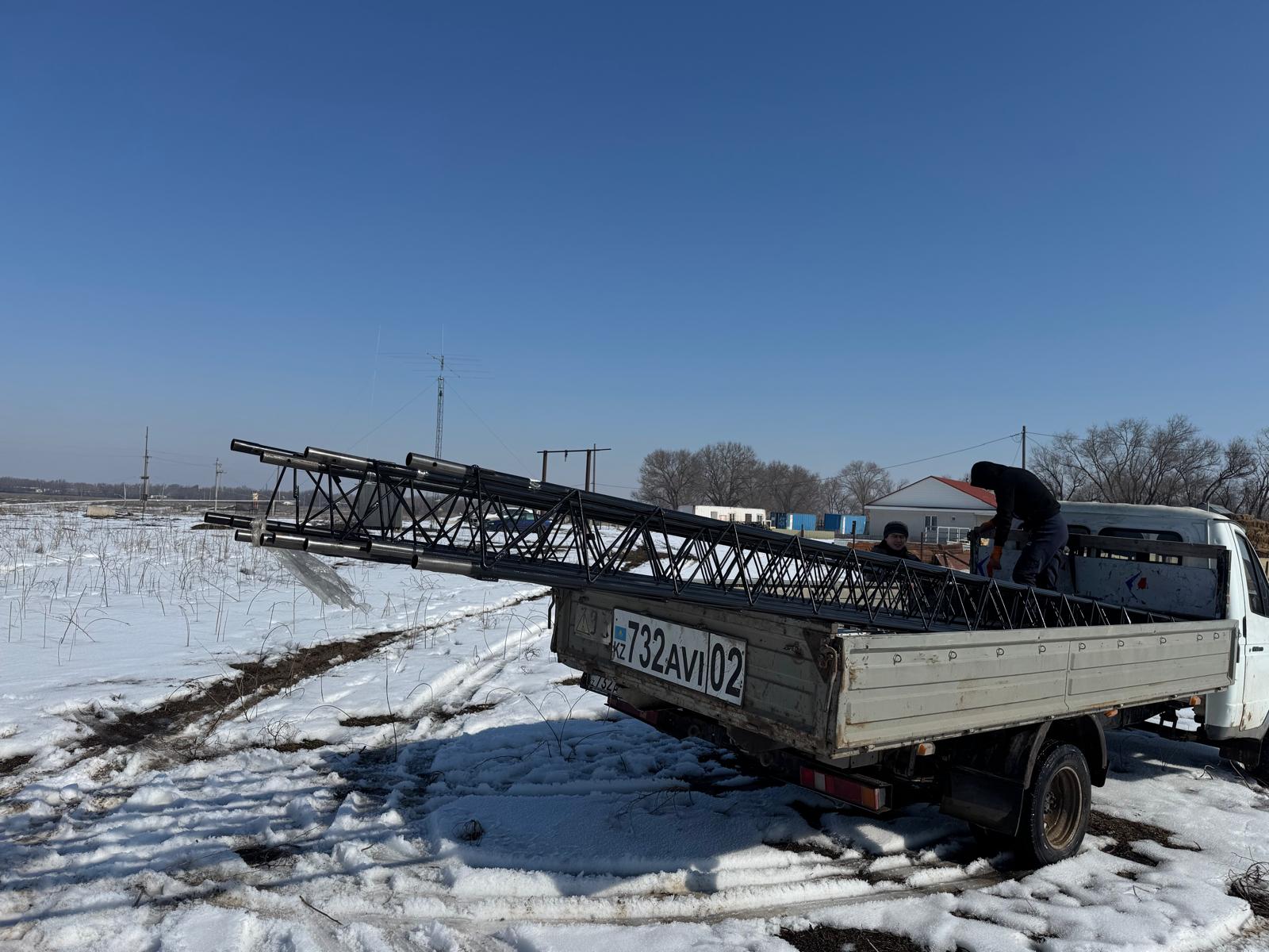
We brought the antenna from the place I assembled it to the tower. It is possible with four people on hand, though some special coordination is required since the antenna is heavy, bulky, and has high inertia.
Thus, from the previously planned steps:
- Assemble three more orbital bearings – done with caveats
- Assemble six more sections – done
- Bring everything to the site – done
- Finish the 40-meter Yagi – Not yet finished with a few supporting guys missing. The Yagi still has to be raised for the top section; the fixture needs to be reworked since the section size changed (32mm tubes turned to 42mm tubes); tested and tuned, and the returned to the ground
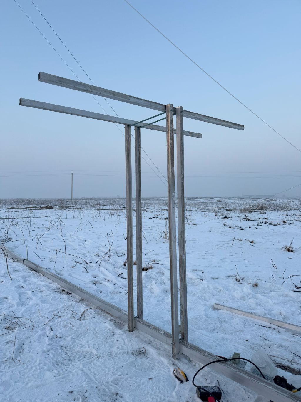
- Temporarily install the top section vertically and raise the 40-meter Yagi to it, and attach it. Tune the elements to the band properly – not yet done. The section is installed, but the antenna is not raised or tuned yet
- Design and assemble a 20-meter Yagi and install it below the 40-meter on the same top section as the 40-meter Yagi so that they will be raised on the top together – not sure I will do that. It is smart. However, I want to finish the project and not over-complicate it. Time flies too fast. But by the time I finish the project, I may need to leave Kazakhstan altogether – who knows? It is contra-intuitive since the rotating tower makes sense when multiple antennas are installed on it. But now, even if the tower is raised successfully, I will be very happy. If we install the antenna there – it will be amazing. If the tower rotates somehow, it will be truly unbelievable. Like it was put in the old social advertising: “Make sure your goals are realistic.” (in Russian but very philosophical and funny 🙂
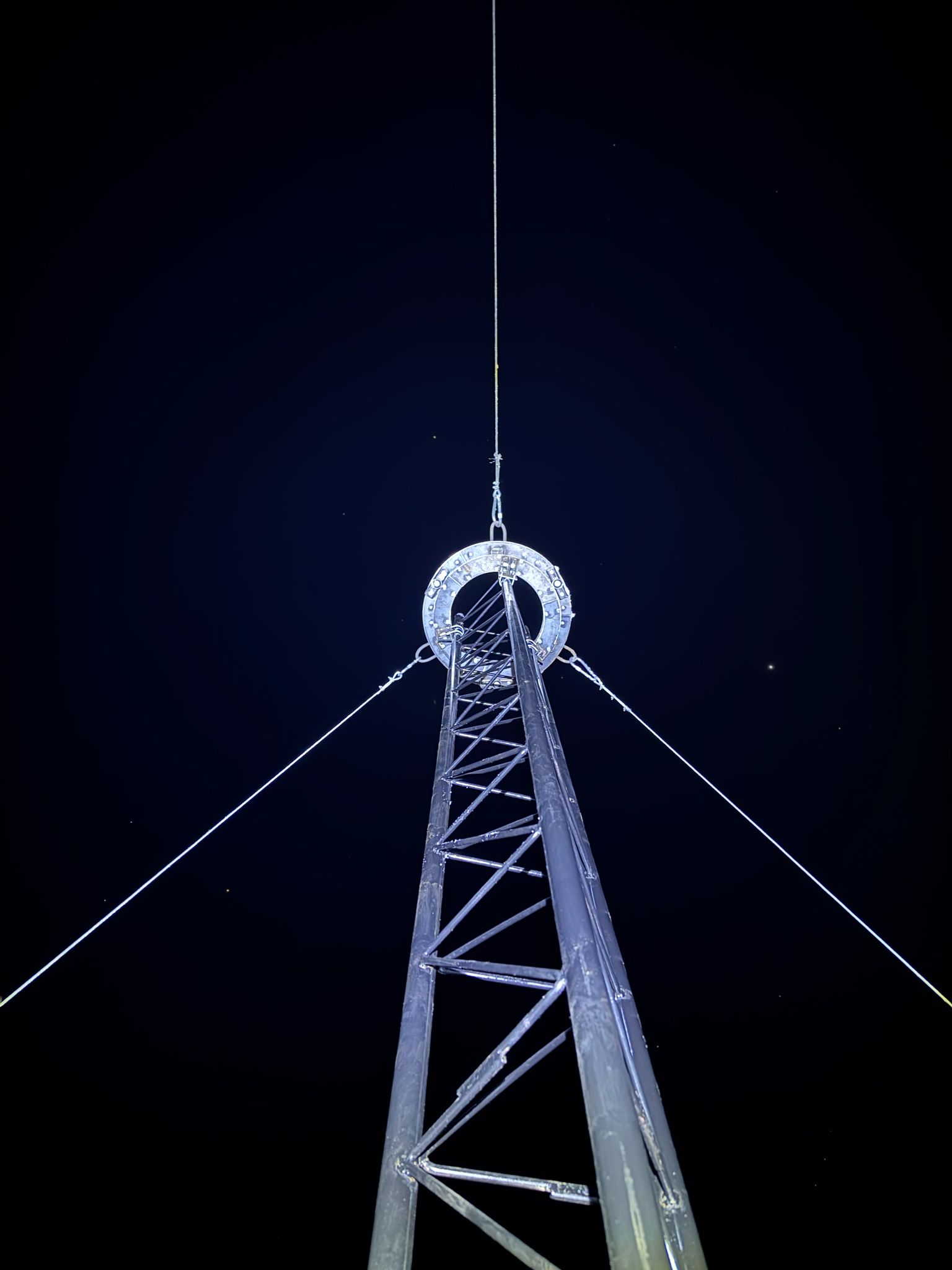
2025.Feb.16
In the last few days:
- The first (bottom) mast section arrived to the site
- The rotating table and the first orbital bearings were brought as well
- Some additional materials – anchors for guys – were prepared as well
- Well after the sunset – literally in the darkness – we installed the version sections and enjoyed that it is rotating
- It is not guaranteed that everything will work, eventually, but so far so good, which is always encouraging
- Oh, yes, the rotator was shipped from China as well. It shall arrive in about two weeks in Almaty. I will hope to install the full tower to its full length by that time
The next steps:
- Assemble three more orbital bearings
- Assemble six more sections
- Bring everything to the site
- Finish the 40-meter Yagi
- Temporarily install the top section vertically and raise the 40-meter Yagi to it, and attach. Tune the elements to the band properly
- Design and assemble a 20-meter Yagi and install it below the 40-meter on the same top section as the 40-meter Yagi so that they will be raised on the top together
2025.Feb.11
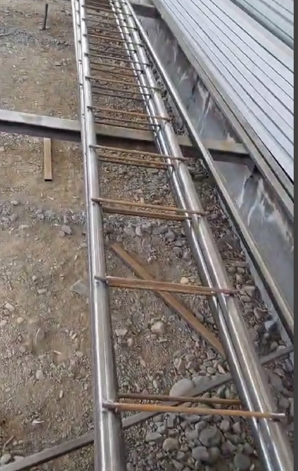
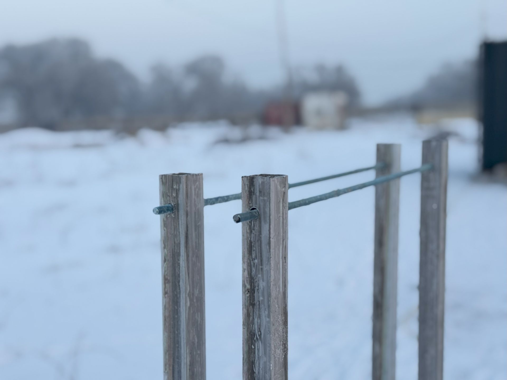
The guys assembling the sections scared me even more. We discussed the design several times. I stressed that it should be a bent 10-mm wire (the design is from the previous tower). The confirmed they understand the task …
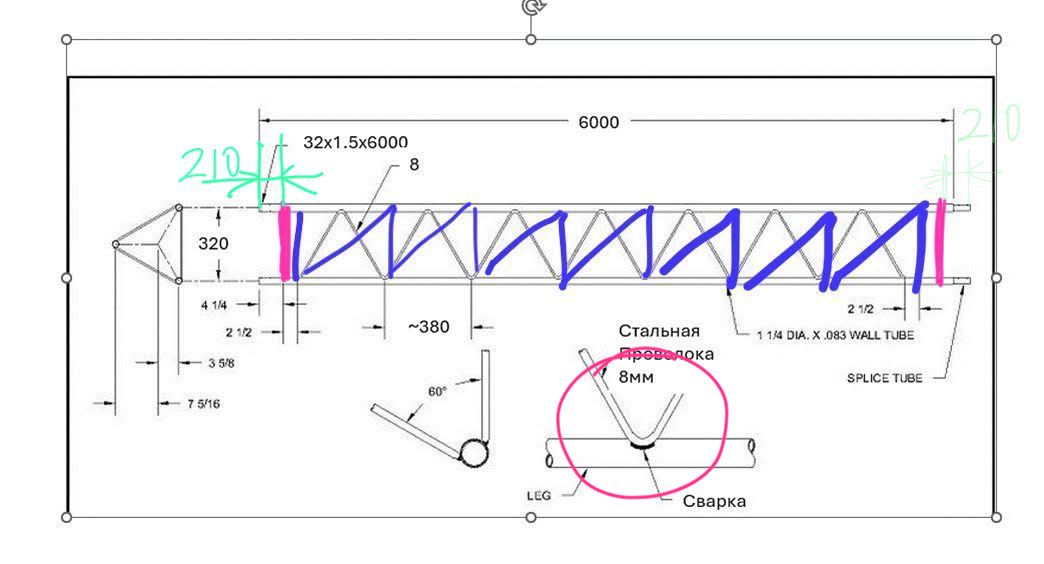
I shared photos of sections of the previous tower as an example …
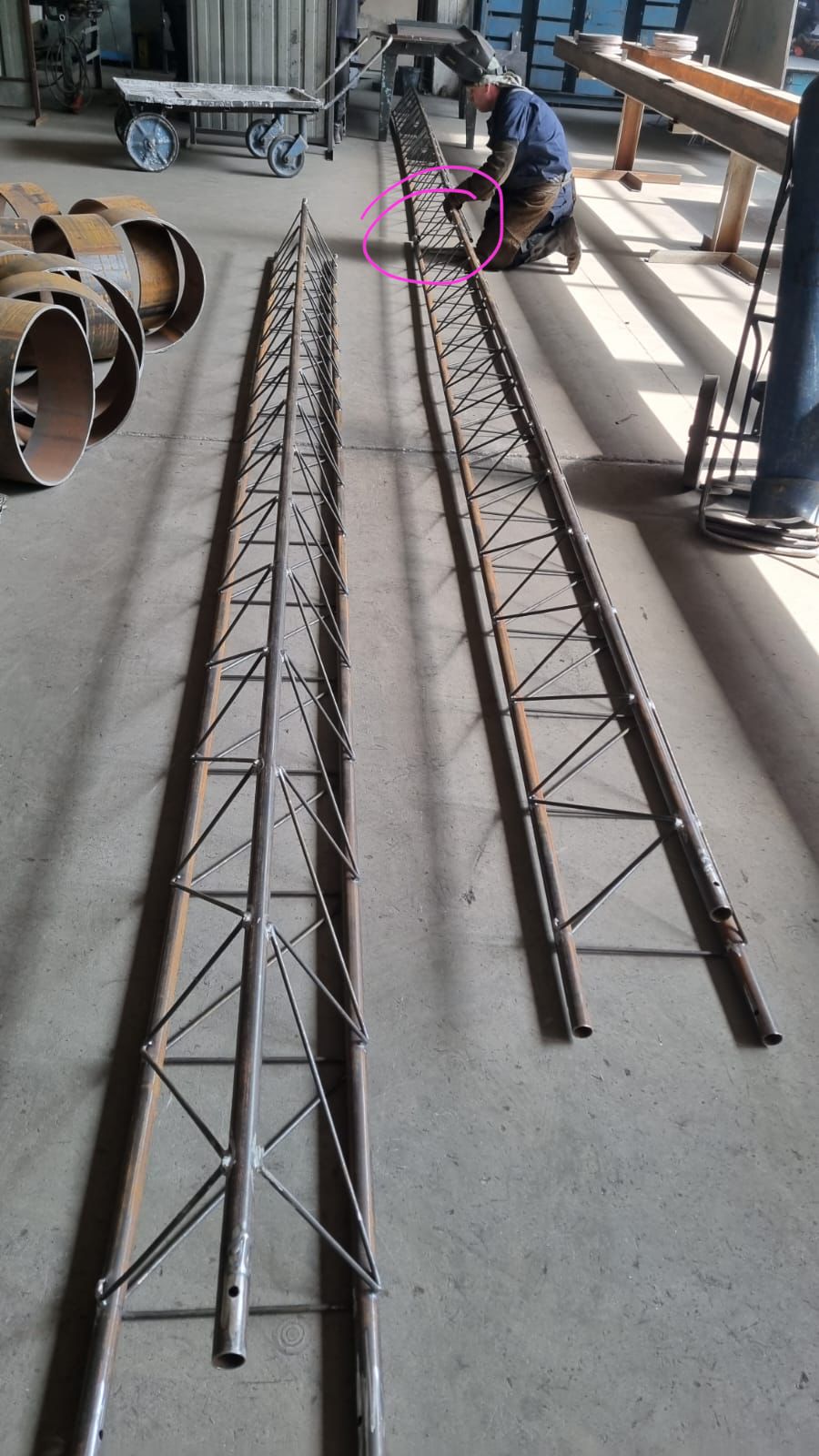
Since I was all the time asking to share the progress to prevent any possible issues or a need for rework, the first thing I saw this morning was that they cut the wire instead of bending it as agreed…
2025.Feb.10
The last two days were very active:
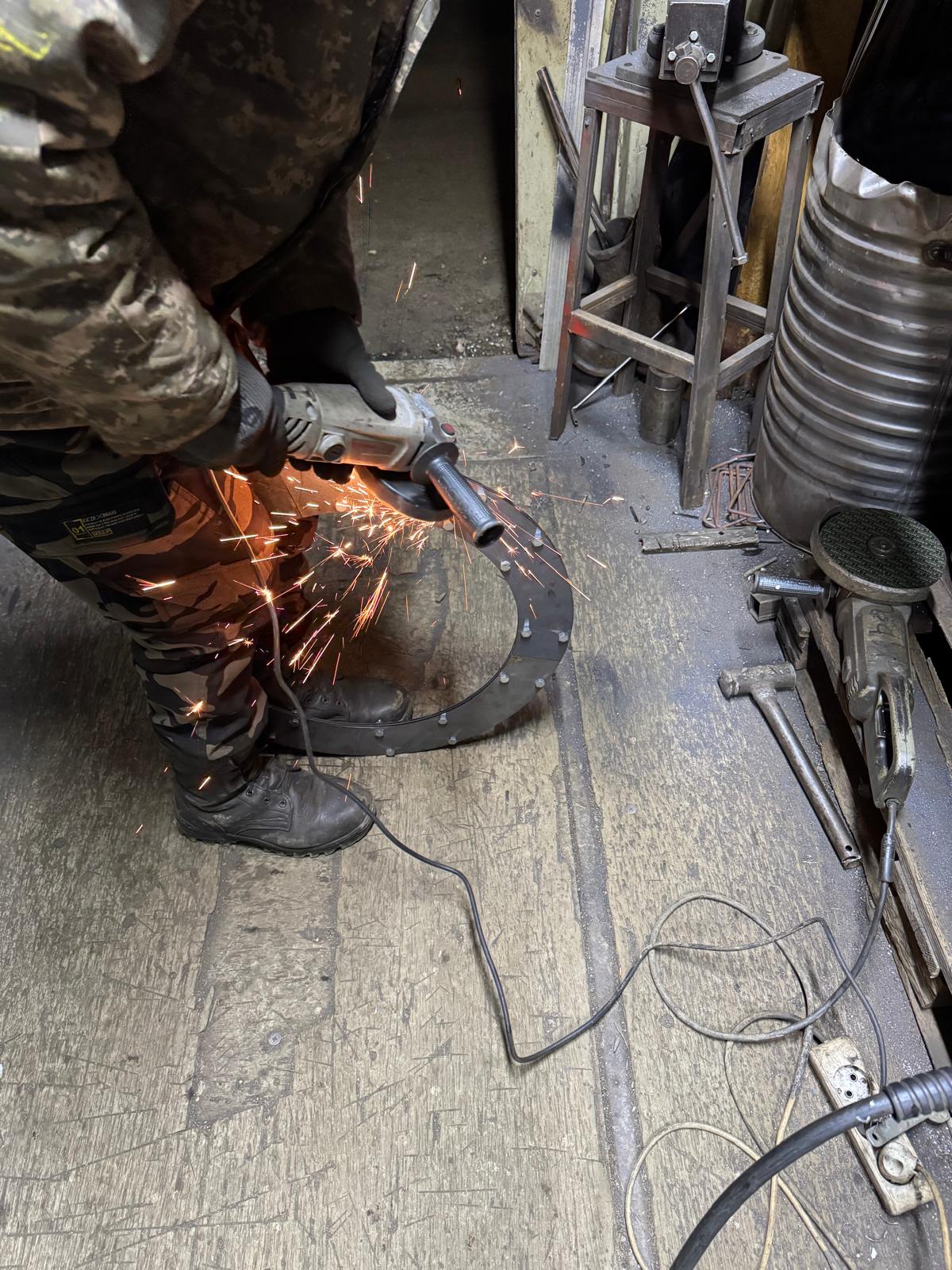
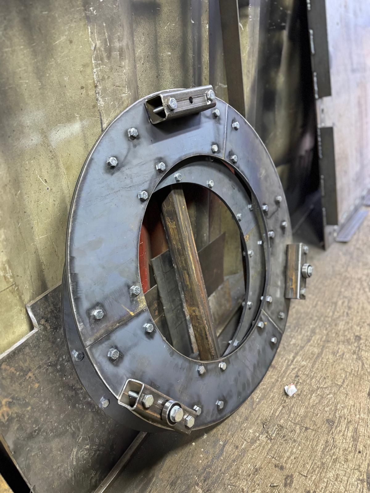
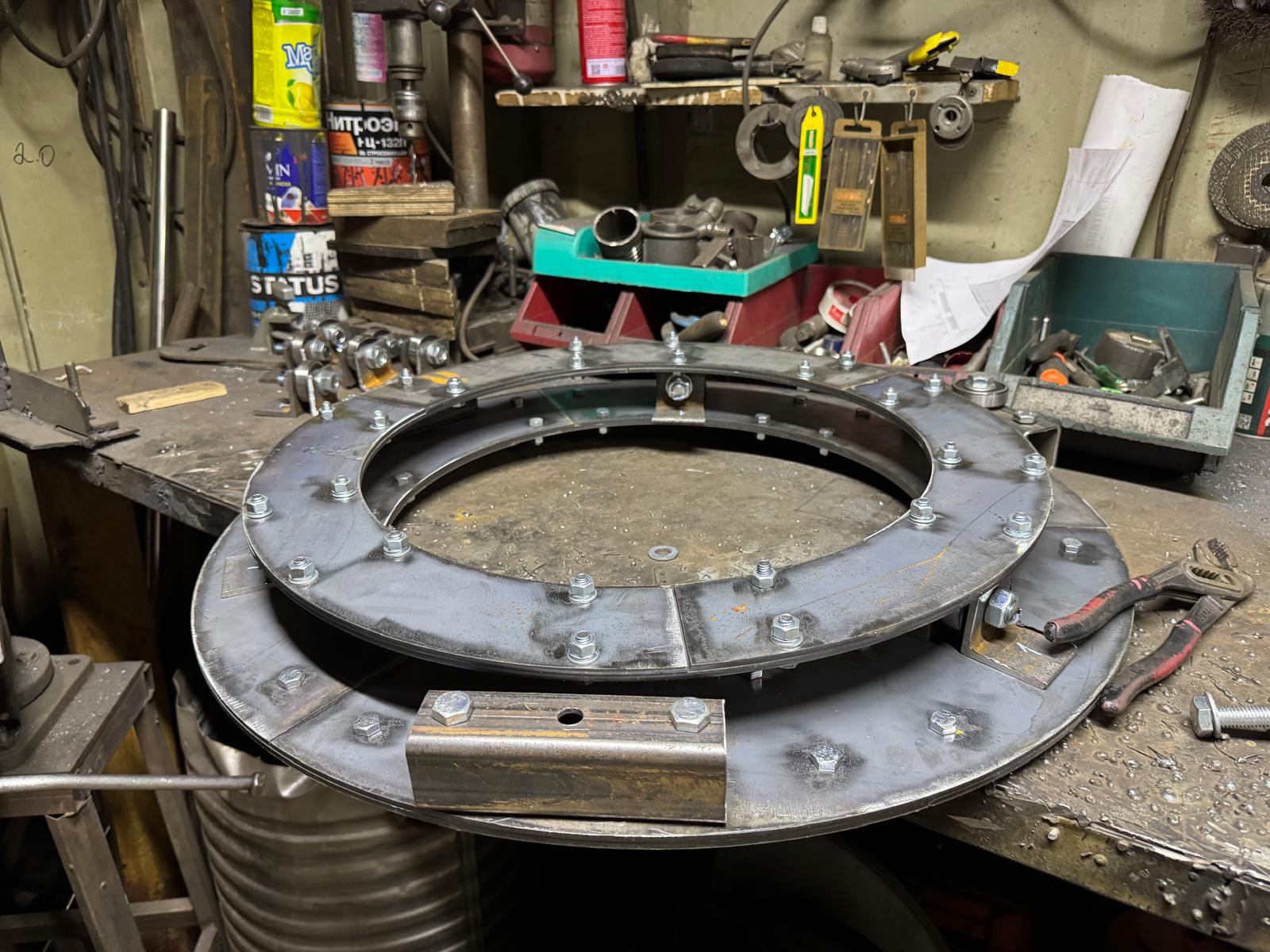
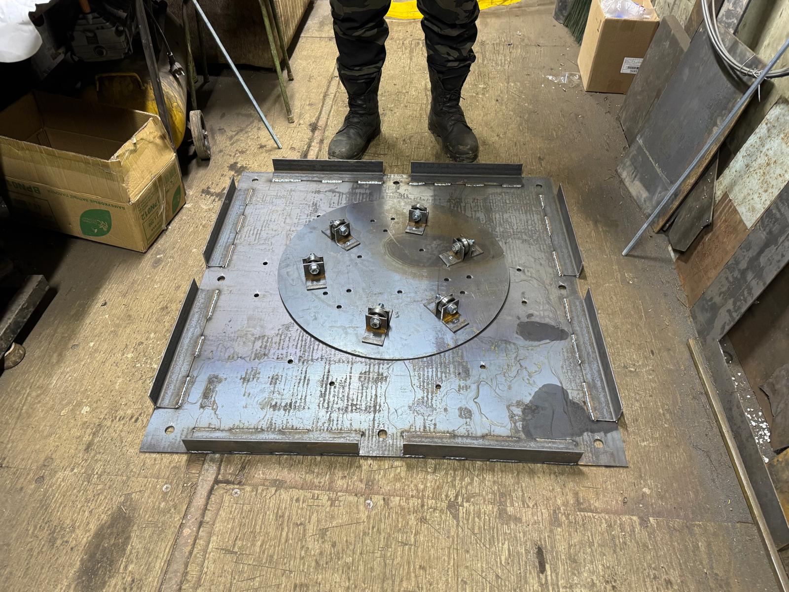
- The rotating table and the first orbital bearing are done. It is unclear whether they are strong enough, where the metal can live long enough, where tolerances are small enough … Thus, a real test in the field with a smaller 6-12-meter tower is required 😉
The last two days were very active:
- The rotating table and the first orbital bearing are done. It is unclear whether they are strong enough, where the metal can live long enough, where tolerances are small enough … Thus, a real test in the field with a smaller 6-12-meter tower is required 😉
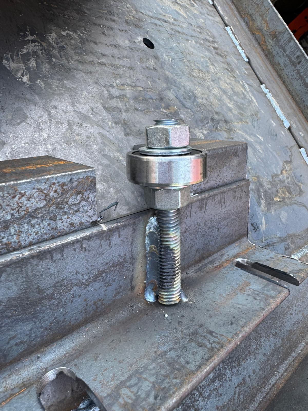
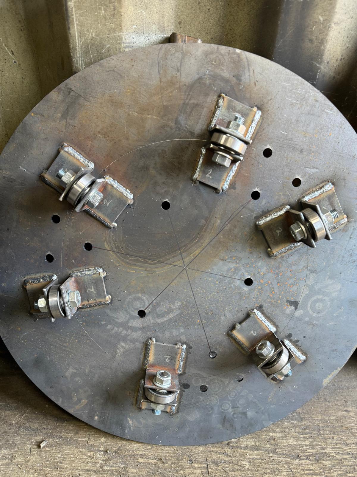
Current issues, uncertainties, and changes in the design on the fly:
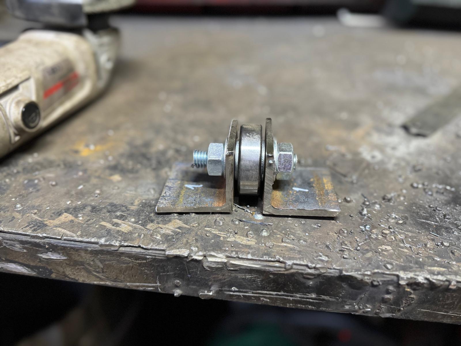
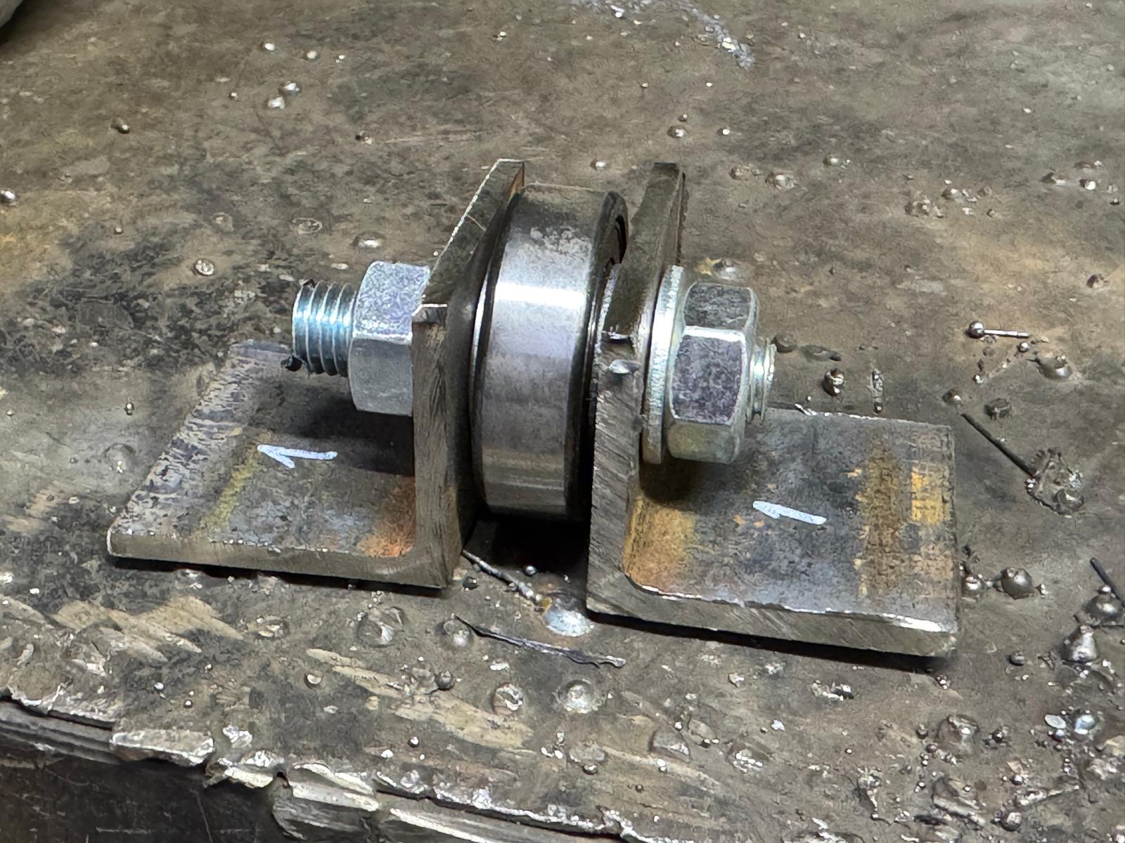
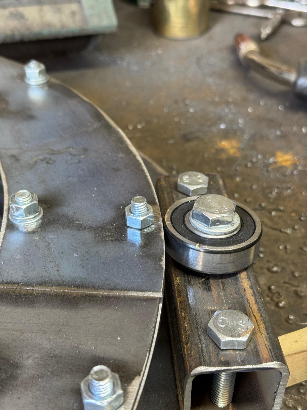
- The orbital bearing and rotating table disks are wobbling too much. There is a high risk that they may jump from the side bearings completely. Potential solutions:
- Install the section on the rotating table and see the performance under the real weight. It shall pressure the metal of the table and minimize the wobbling. The same goes for the guys pressing the disks of the orbital bearing down. The real tests with 1-2 sections of the tower are required
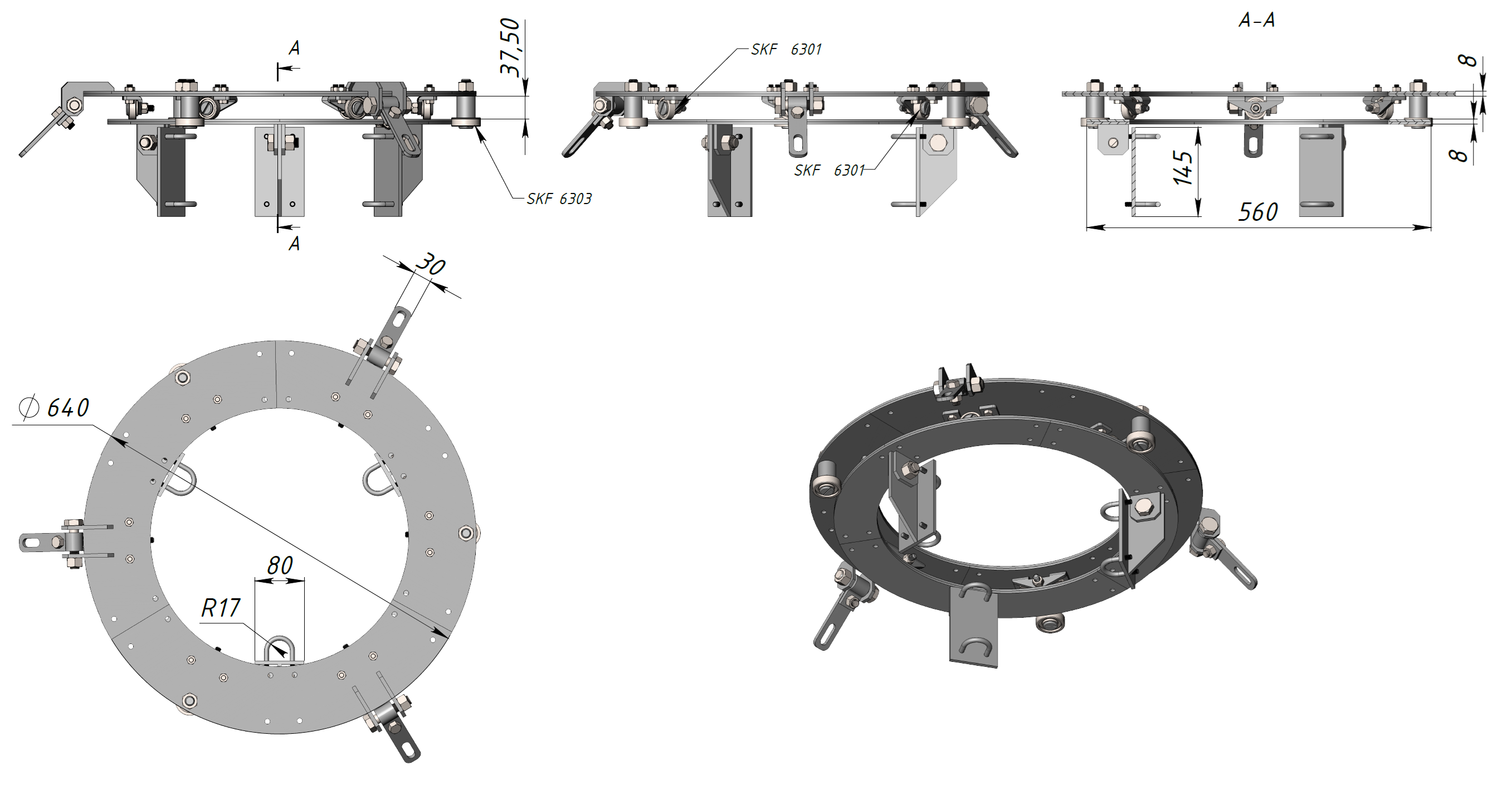
- Use two bearings on the perimeters of the disk on top of each other instead of one – the resulting bearing will be thicker. Or find and install thicker bearings. Currently – 12mm (6301 bearing on the side for the rotating table and 6303 for the orbital bearing). This will reduce the chances of the disks jumping off the bearing completely under pressure, wind gusts
- Install the section on the rotating table and see the performance under the real weight. It shall pressure the metal and minimize the wobbling
- There was no metal with the proper dimension for some elements of the orbital bearing. Changes in dimensions for those elements lead to changes in the dimensions of other elements
- Too little margin was left in between the rotating table and protective elements on the perimeter. The protective elements’ height was changed
- The design of the side bearing for the orbital bearing was changed because the dimensions didn’t match somehow. The bearing was changed from 6301 to 6303
- It is not obvious that the rigidness of the plates for the orbital is sufficient. Maybe there must be a vertiсal ridge welded on top of the bearing disks for additional rigidness
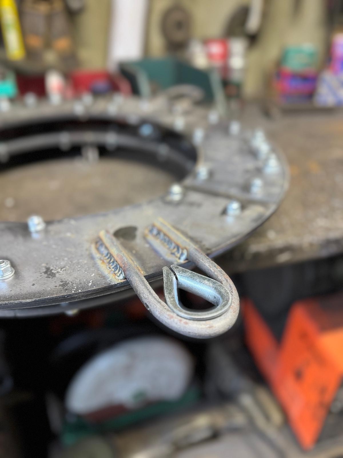
- The design for guy “ears” was changed on the orbital bearing. Previously, there was a completely different design with two elements. Everything was greatly simplified … I very hope we haven’t made a major design mistake with that
- It is not obvious whether the metal is suitable at all – it may be too weak – and the stronger steel of the bearings will make deep threads in the supporting metal too quickly and it will be too difficult to rotate the tower and will stuck
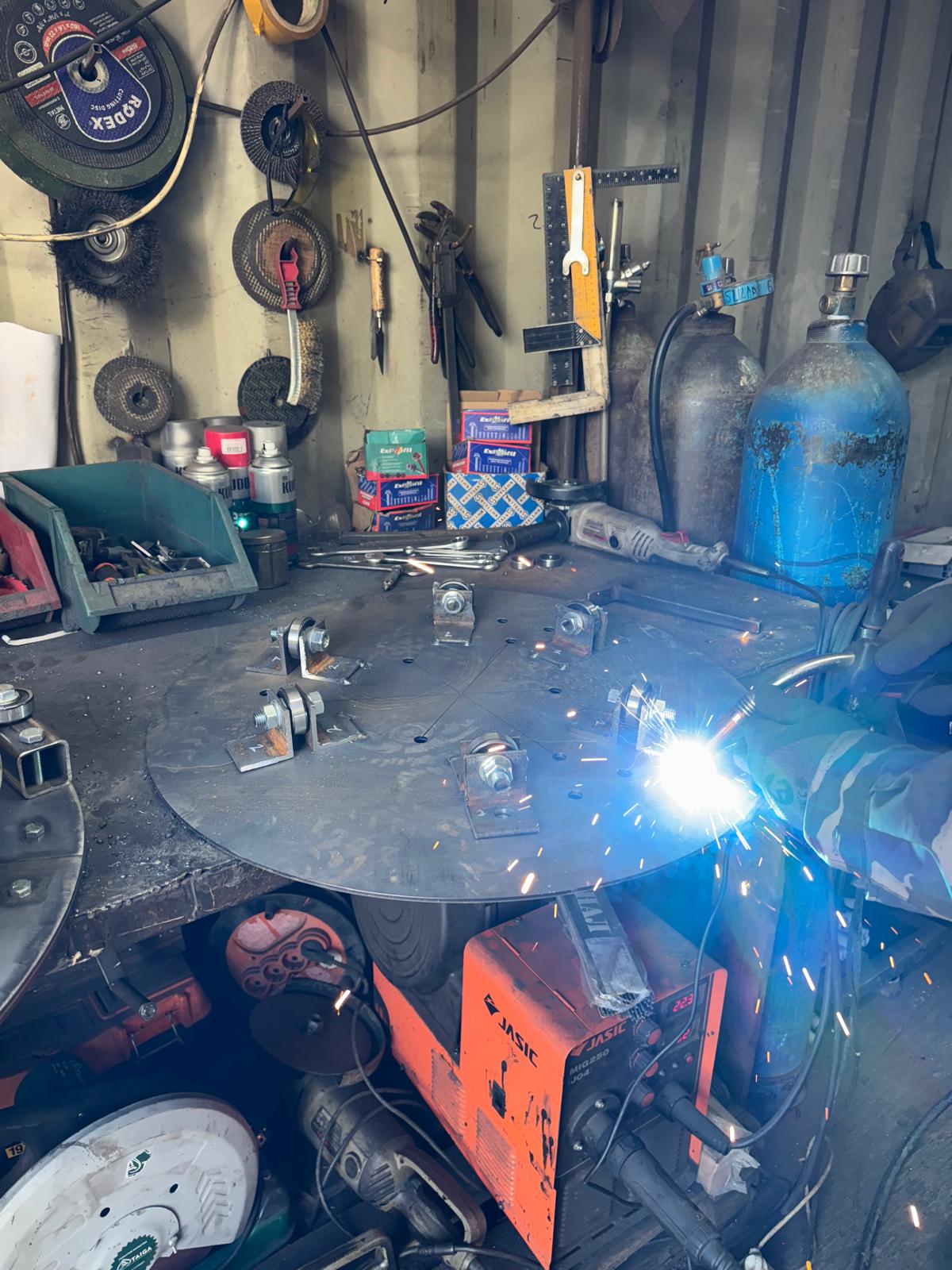
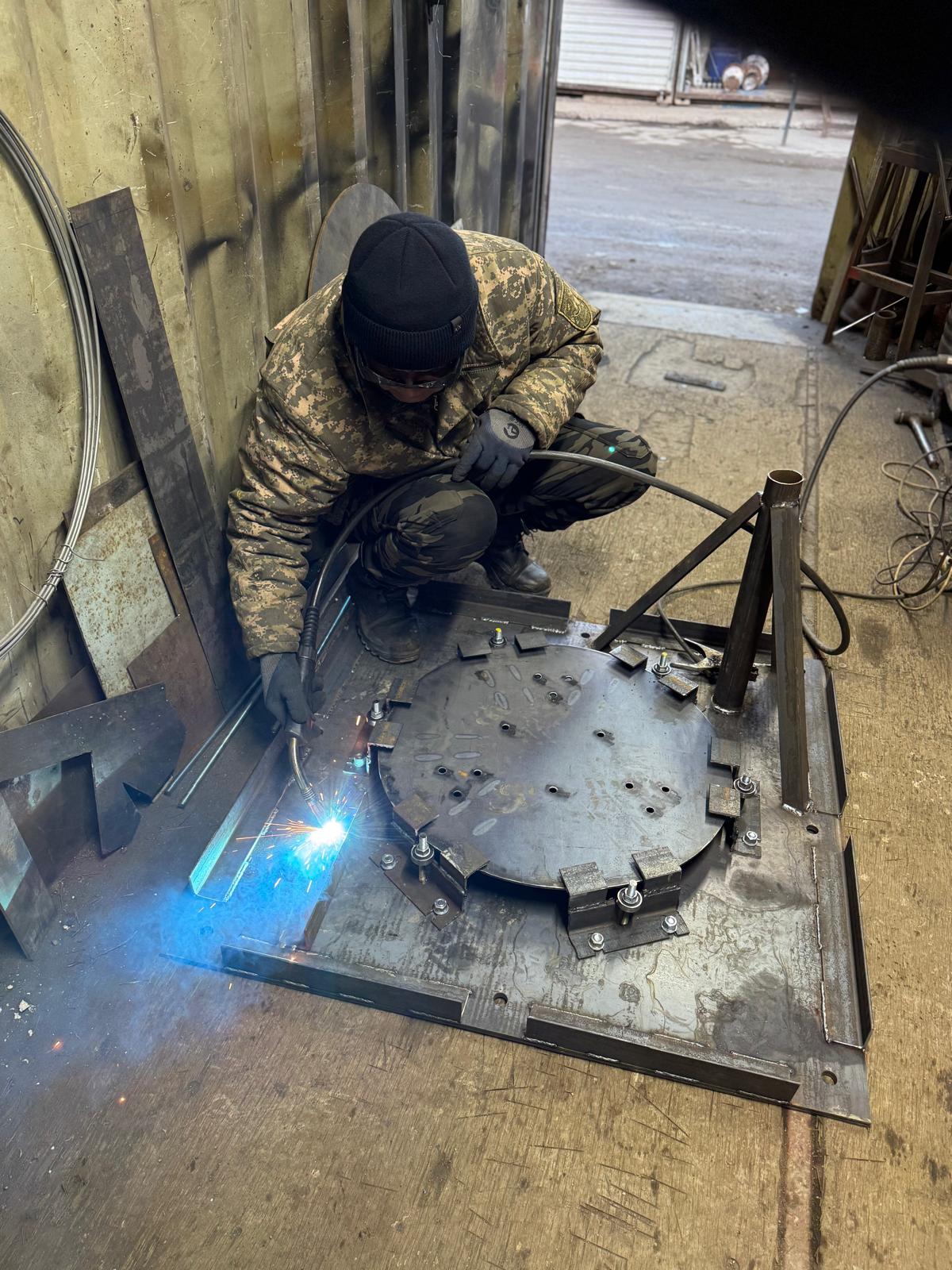
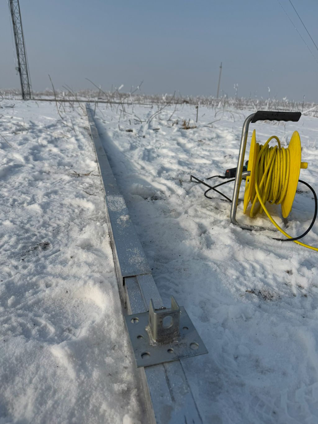
In the last moment, I asked to weld a special support for the 6-meter jig pole that will be used to raise the bottom element of the tower. I cannot call for a crane for such a small work. Thus, some heavy lifting must be done using basic tools, with the help of a wincher, and by myself only. The support shall help with that.
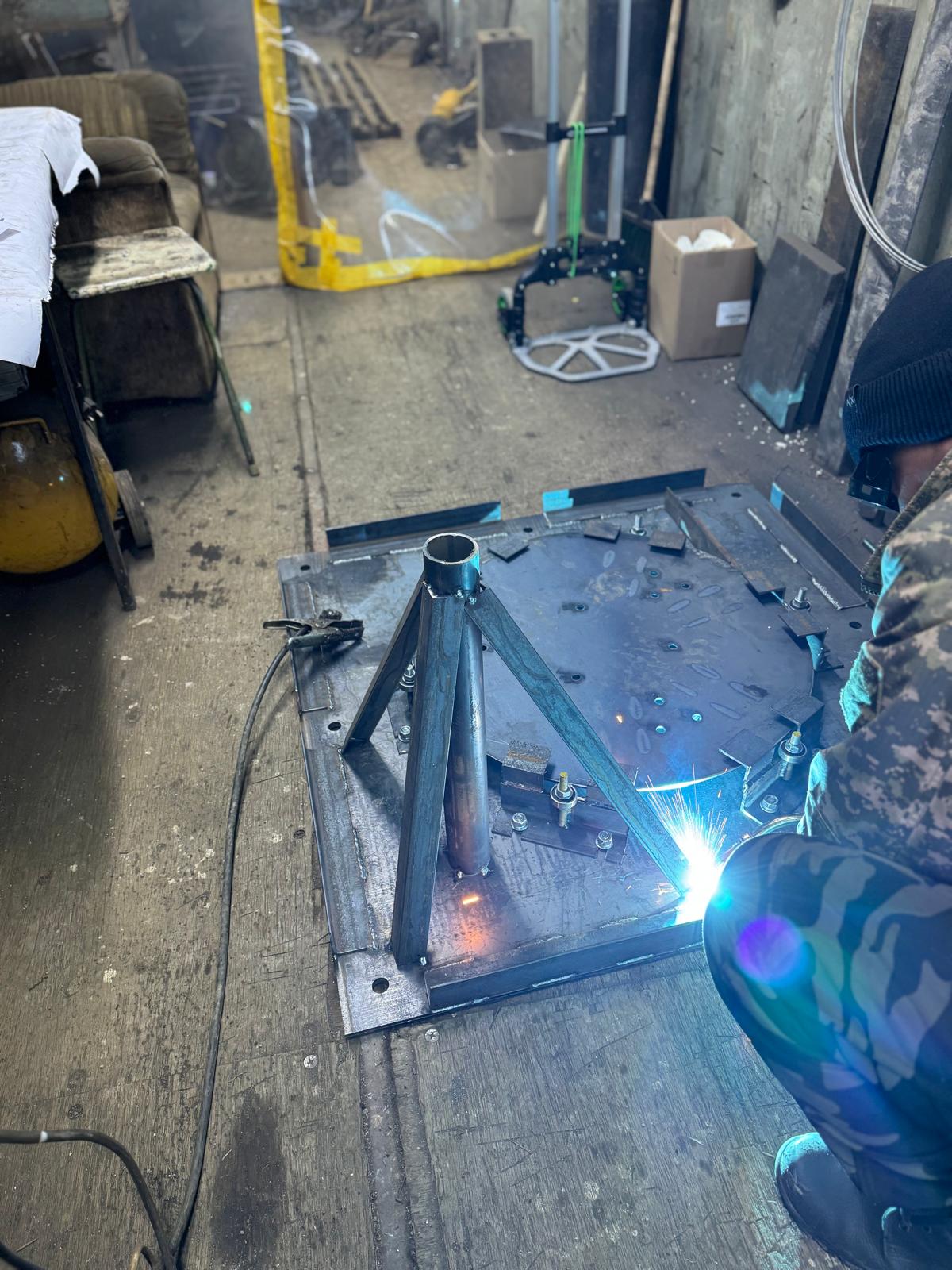
On the opposite corner, we welded bottom elements for the rotator’s future support. Since China is finally back from its long Chinese New Year holidays, it is time to select and purchase the rotator. It will take about two weeks to arrive. By then, it would be great to install the tower or at least a few of its lower sections and see whether everything meets expectations.
Since the rotator has yet to be purchased, we made a base so that different types of mounting structures can be installed on it with drilling since welding won’t be available on the QTH.
In a parallel world of making the mast sections, scary news came:
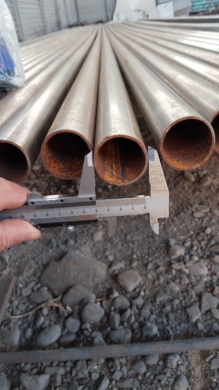
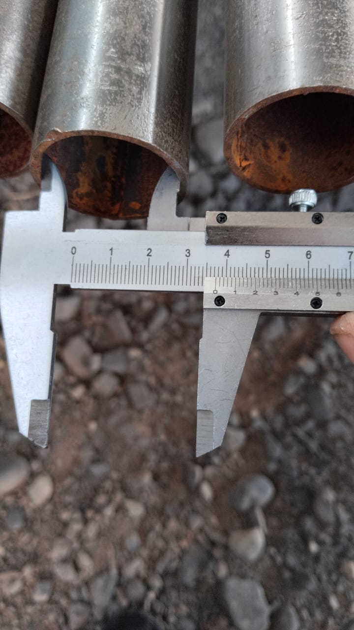
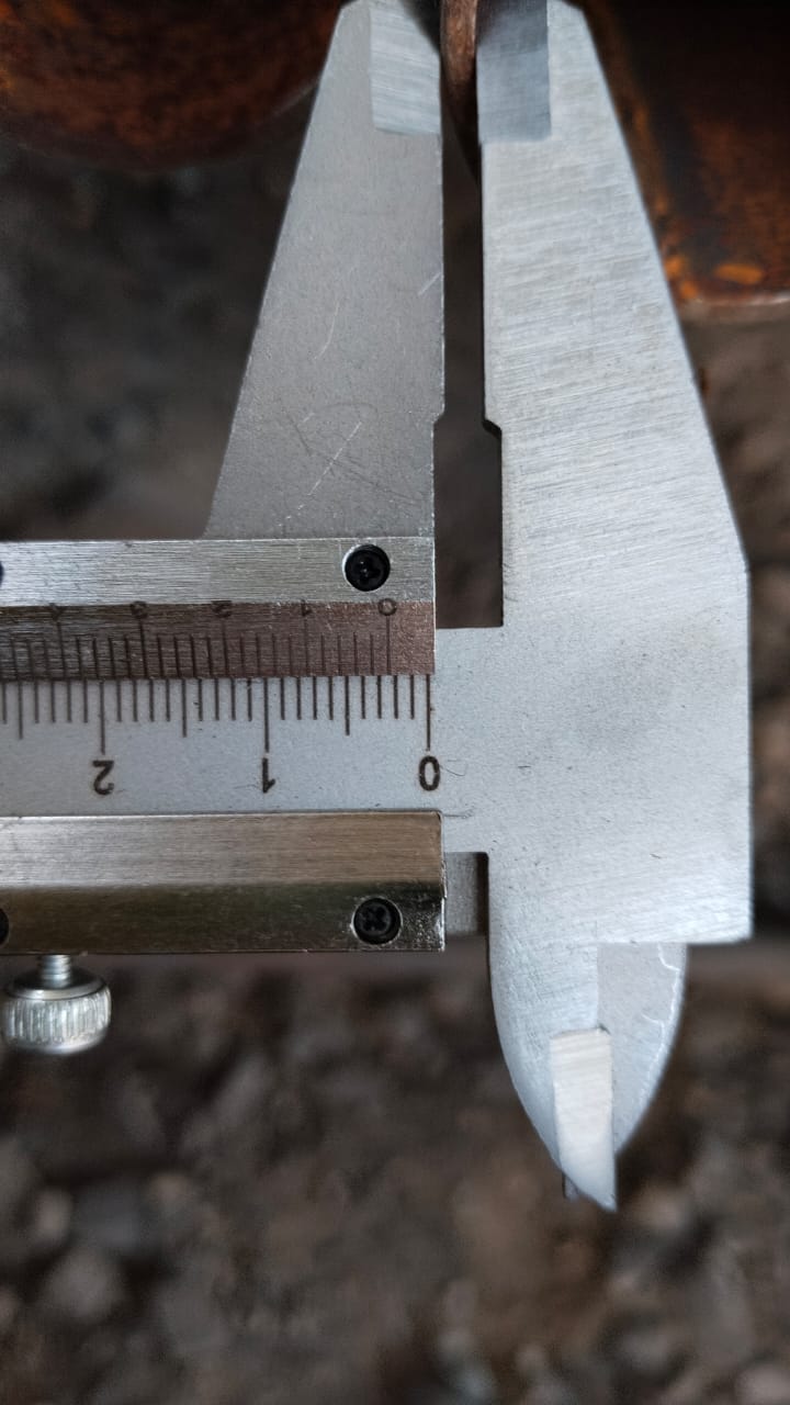
- The guys who do the masts sections (7x6m) cleaned the tubes from the rusts and only then discovered that they are not 32 mm in diameter as they were supposed to be but 42 mm … I wonder how it is possible to confuse the 32-mm tube for the 42-mm tubes … either they are highly unprofessional or there is no proper control. Both options are not encouraging since I need to rely on the quality of the sections very much
- The design had to change on the fly as well since different diameter of the tubes will be used
- They will be stronger, which is good. But they will be heavier. Which is bad. I am not sure what is better
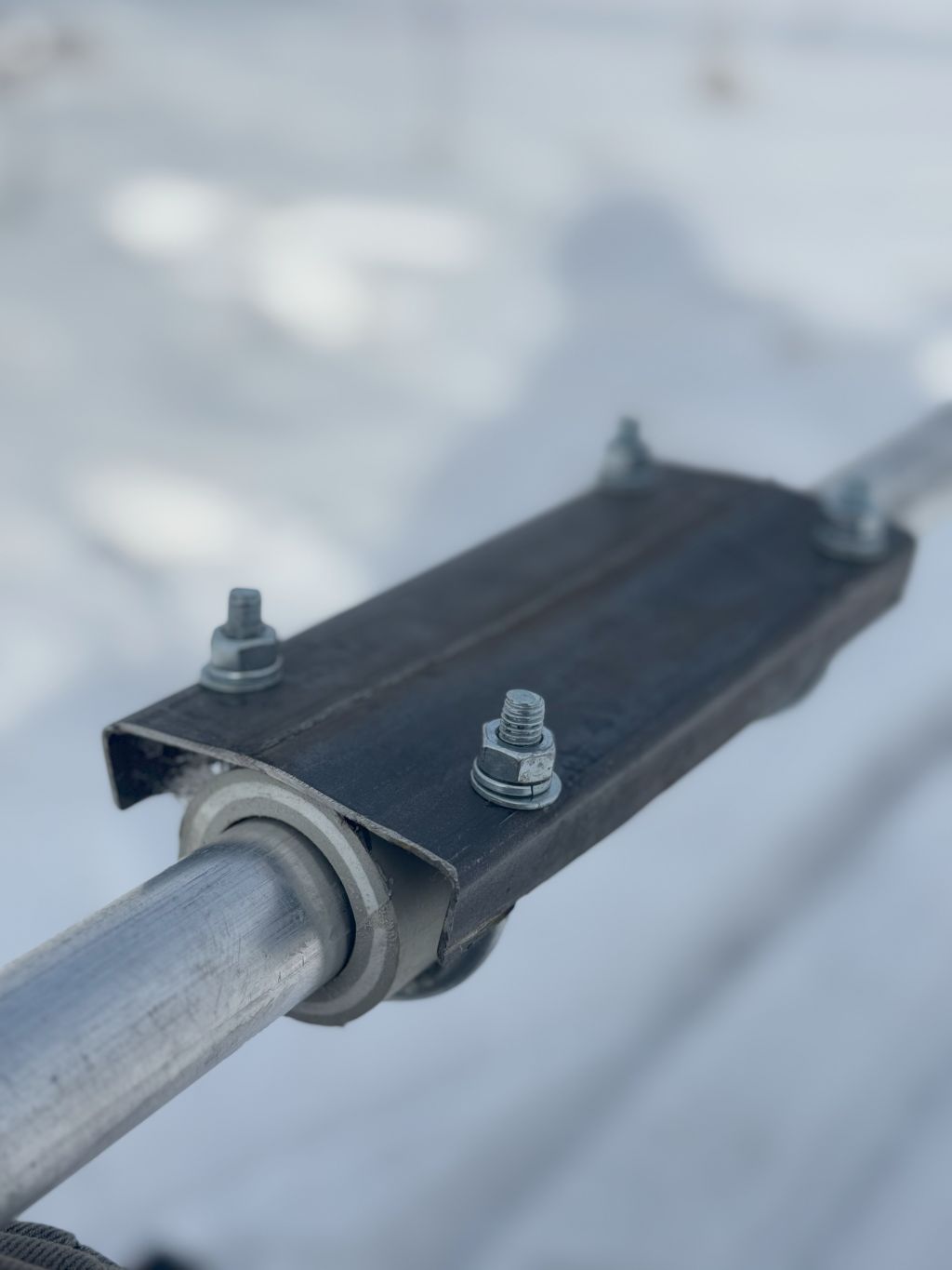
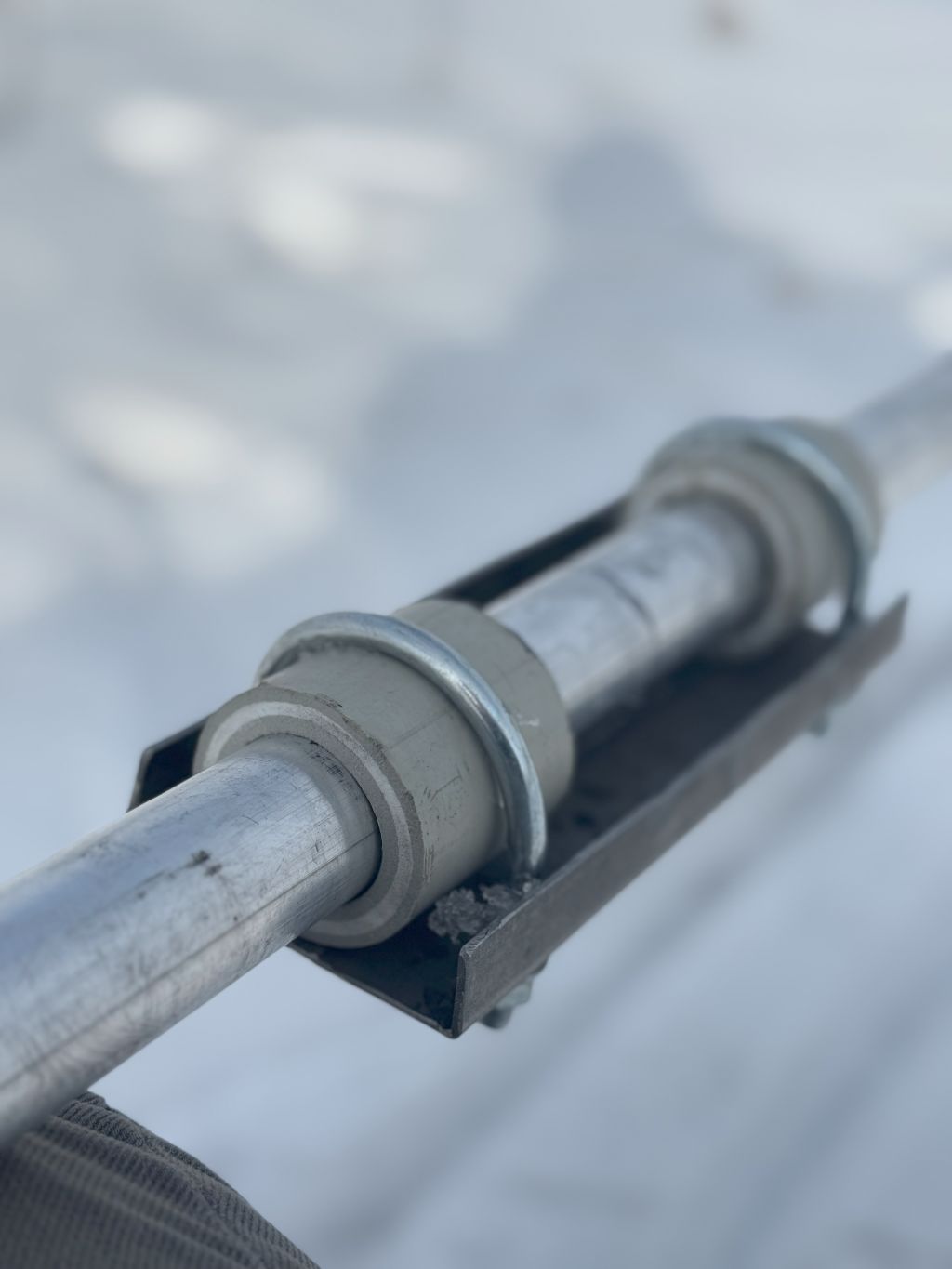
Since it takes so much time to assemble the orbital bearing, it was worth changing the design of the connection between the sections. The flange won’t be used as planned because it wouldn’t fit inside the diameter of the orbital bearing without the bearing disassembly. Instead, thicker outer tubes of 40-cm length will connect and hold the sections together.
It will also impact the design of the bearings. It will be simpler – not need to assemble – but more expensive because the inner disks will be just cut off and not used. But the disks will be flatter as well. So, the overall design will be better.
2025.Feb.01
Since the antenna is mainly done, I haven’t done much about it since the last visit:
- I sent multiple requests for the masts. A couple of prospects for production are identified. It’s not as great a factory as before, but it’s already something reasonable cost-wise and potential quality. Ready to order on Monday. But perhaps, I won’t hurry since a few elements for the rotator and orbital bearings shall be ordered along
- Order a crane. It is an easy option, but so far, the prices have not been appealing at all. If you check websites – more than comfortable, per/hour. But then you dig deeper, and they don’t offer per hour anymore but per shift, and if calculated per hour, it is 2-4 times more than advertised. I don’t like that kind of cheap lying. So, I’m still searching. Though, it is the most probable option as of now
- Since I put down and raised the tower yesterday, the next option is to use the same approach as with the 10-meter and 20-meter towers – tilt-up method. It is proven and worked. However, for the 40-meter tower, it may be a bad solution:
- Even for the 20-meter tower, using the winch is pretty tough. I am sweating a lot and need to rest several times before I raise the tower. The 8-mm guy sings is like a string. So, it is all close to limits. With the weight of the 40-meter tower, everything may be way beyond the limits, which is dangerous
- There is no point use it after the erection because there will be several antennas on the mast. Thus, I can’t put it down as now anyway. So, the usage will be different as compared to the 10-meter and the 20-meter tower, and the benefits for the option to put the tower down, fix something quickly, and raise it again are none or much smaller than with the existing towers
- To use the gin-pole method. It looks like a nice and independent option. However, it is pretty risky to erect section after section on a rotating tower with multiple levels for guys. Each section is relatively heavy. Everything may take a lot of time. It is much nicer to assemble everything on the ground and to climb the tower when everything is well set and secured with the guys to the ground
In short – many open questions. But the crane looks like the most viable option as of now. By the way, I studied how the wind towers are erected – cranes. Other options are there but cranes – that is what they use. Let’s do simple and proven.
We progressed well with the orbital bearing, though. The first design looks implementable and solid enough. I will be sending requests for quotations tomorrow; thus, some things may change, but the overall design so far looks OK. Of course, everything may change when the tower collapses. But, hopefully, it won’t 🙂
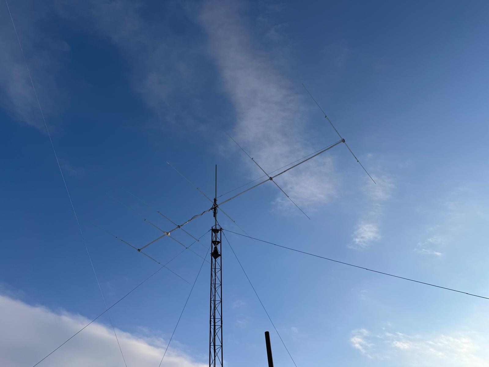
Besides, when I was climbing yesterday to fix the 20-meter and the 15-meter Yagi, the view to the 40-meter is impressive. It is like a newly hatched dragon that doesn’t yet know it can fly. 🙂
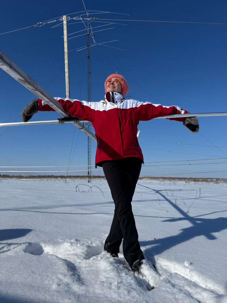
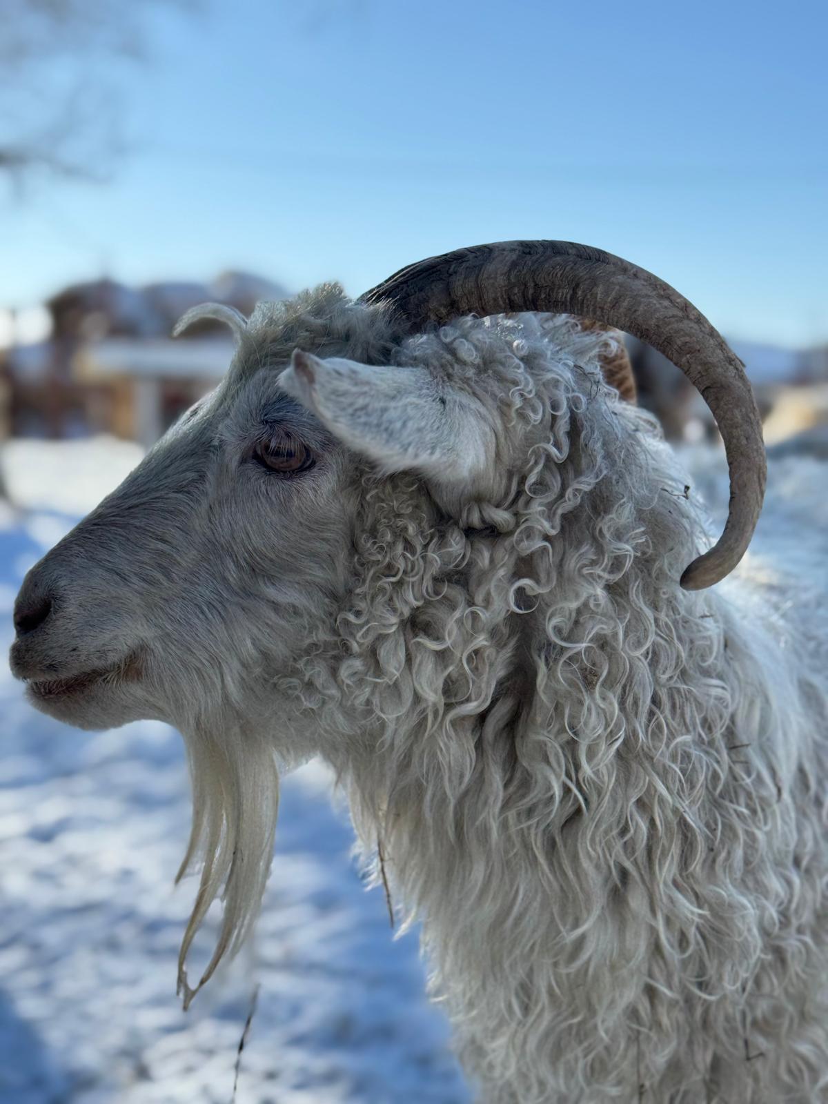
A model advertises the Yagi 🙂

2025.Jan.26
Sunday is the time to complete what has been started earlier.
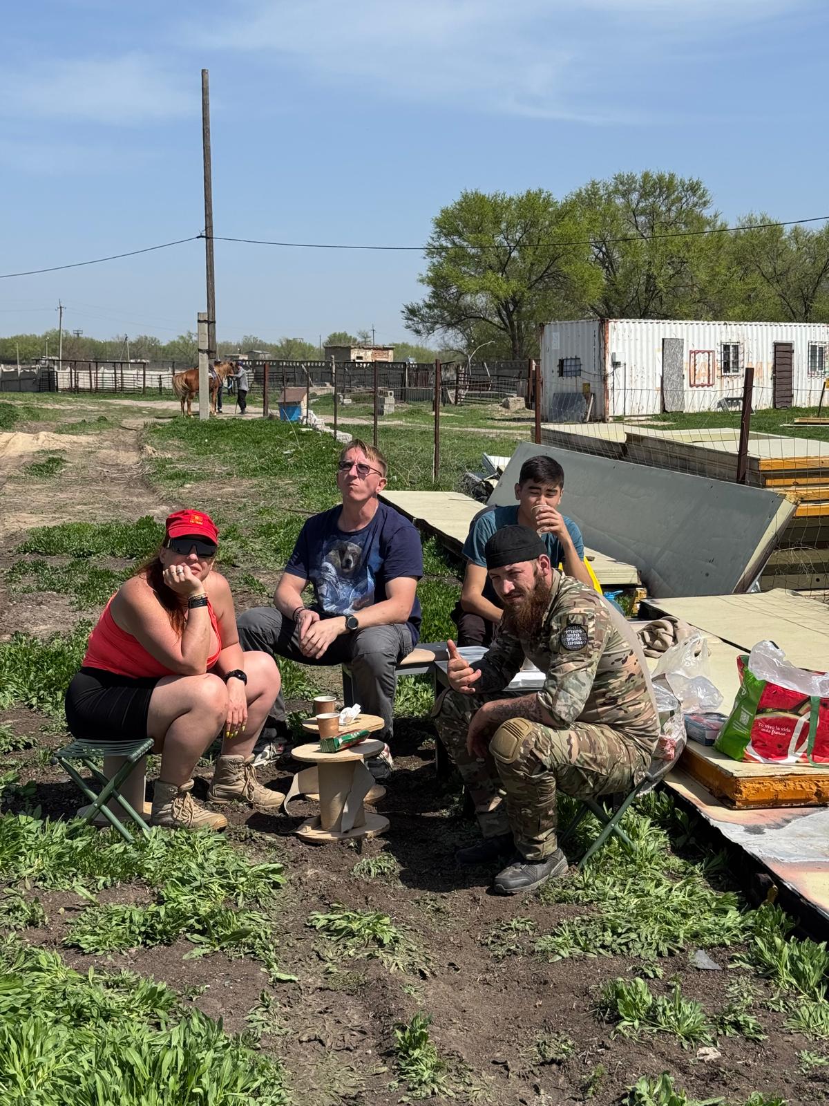
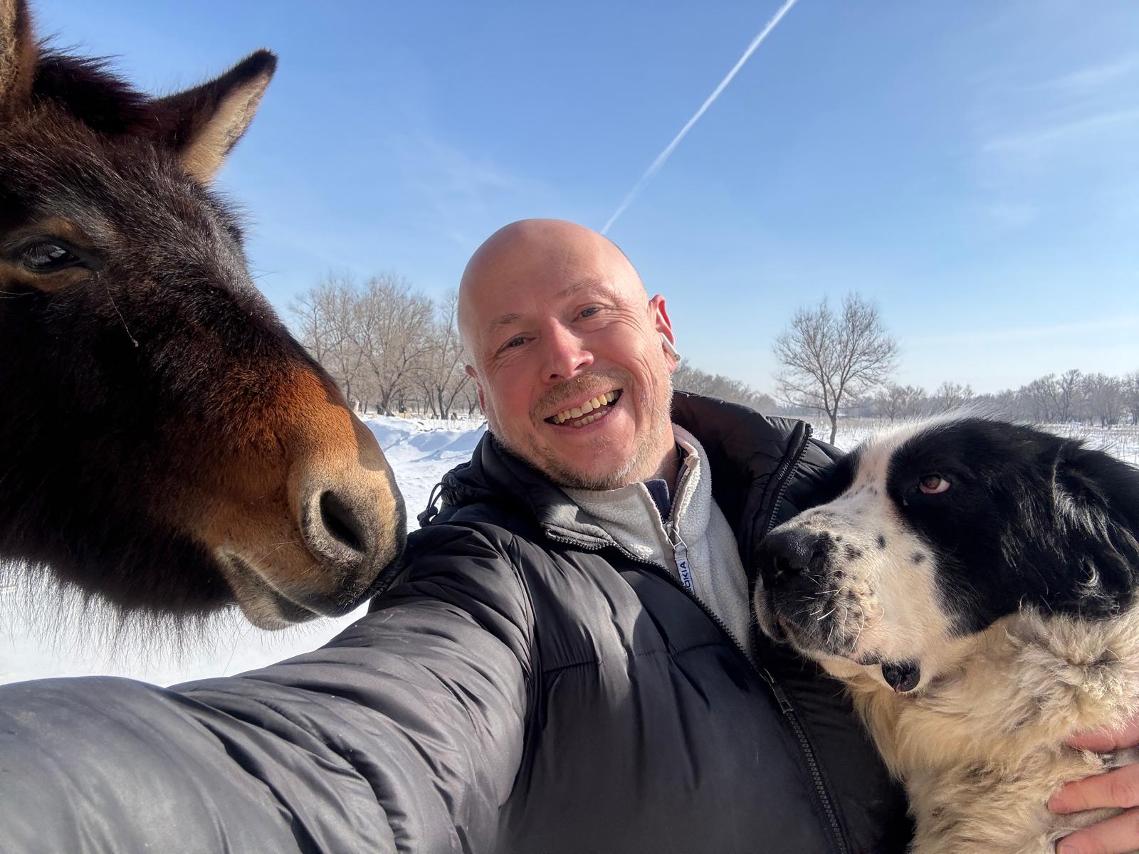
Of course, I couldn’t not visit my friends 🙂
Elements missed the 4-meter tips from each side. It looked like an easy and straightforward work.
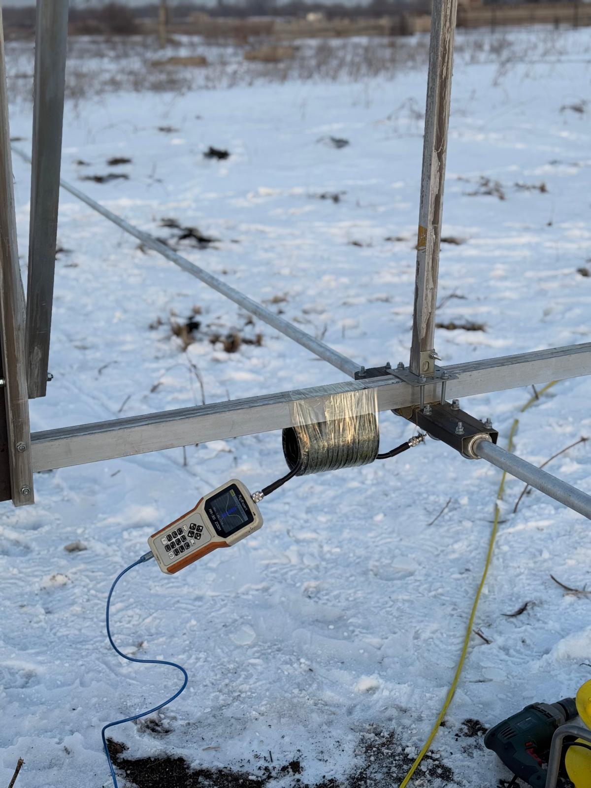
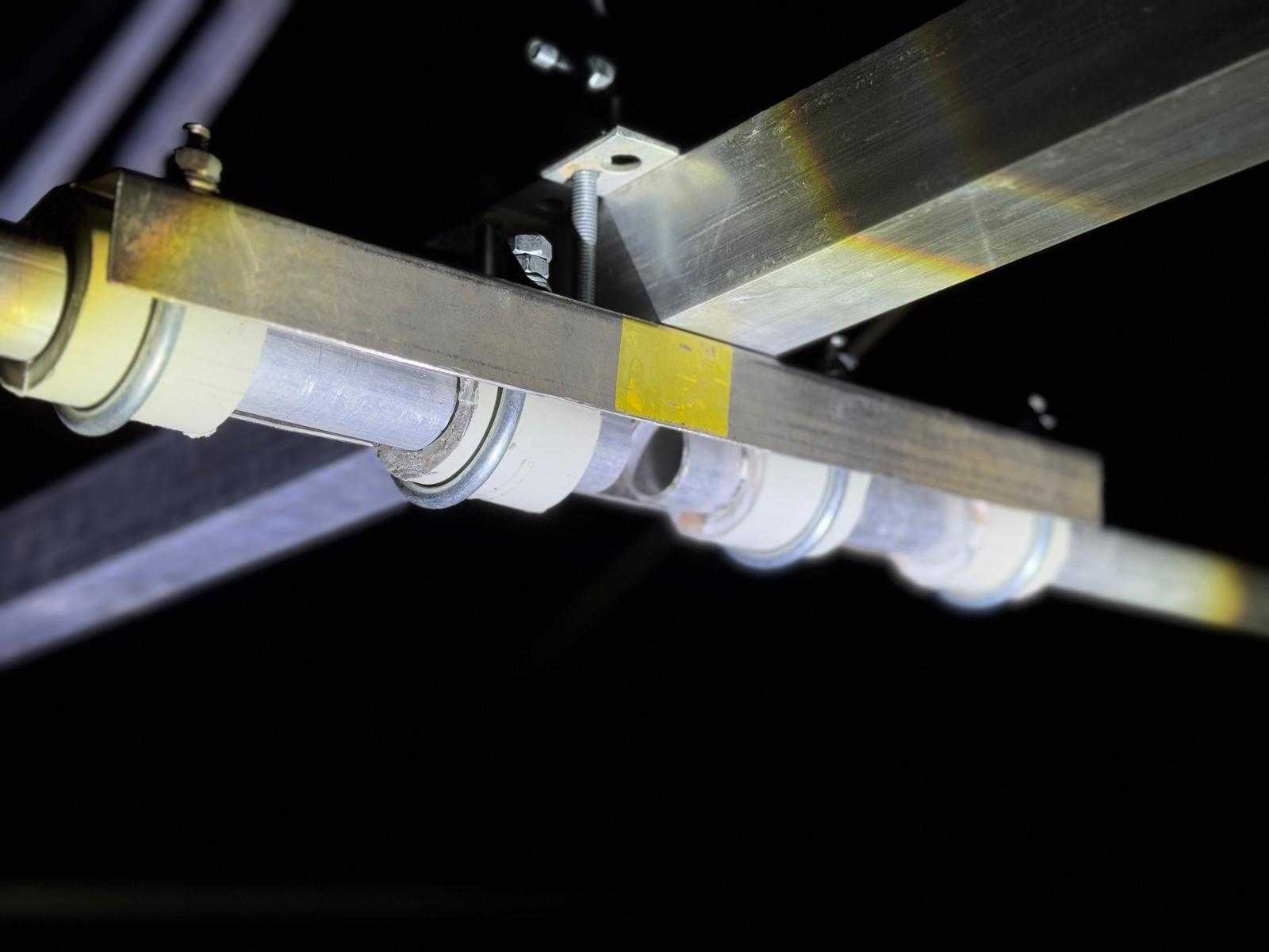
And then – the long-awaited steps – to connect the resonator to the cable and measure the SWR for the first time after nearly two weeks of making the antenna.
The frequencies are just fine. The SWR is a bit higher than wanted. However, the antenna is less than a meter from the ground. Thus, it is not yet a real measurement. But the moment is always very awaited 🙂
It is time to raise the antenna higher … and, as usual, the time is up … – the sunset 🙂
It is not a good idea to climb a slippery ladder… alone … at dusk … in winter … in the steppe … But we are unstoppable in antenna building … and not only 🙂
The second SWR measurement – just before raising the antenna – shows an even better SWR.
Problem 1: Connecting the antenna analyzer via a 5-meter cable immediately killed the nice SWR picture. I didn’t get it.
- Re-measured. The result is the same – not a flat frequency response and higher SWR
- Placed the cable along the boom – to make it perpendicular to the elements and minimize the potential impact. It didn’t help. The resonance wasn’t flat and the SWR wasn’t beautiful anymore …
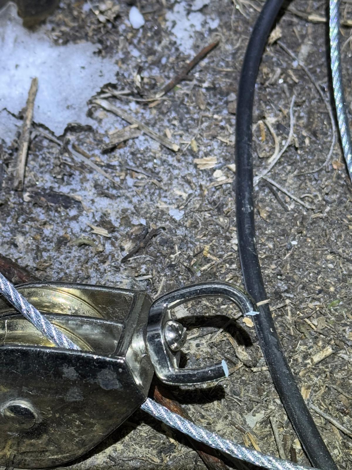
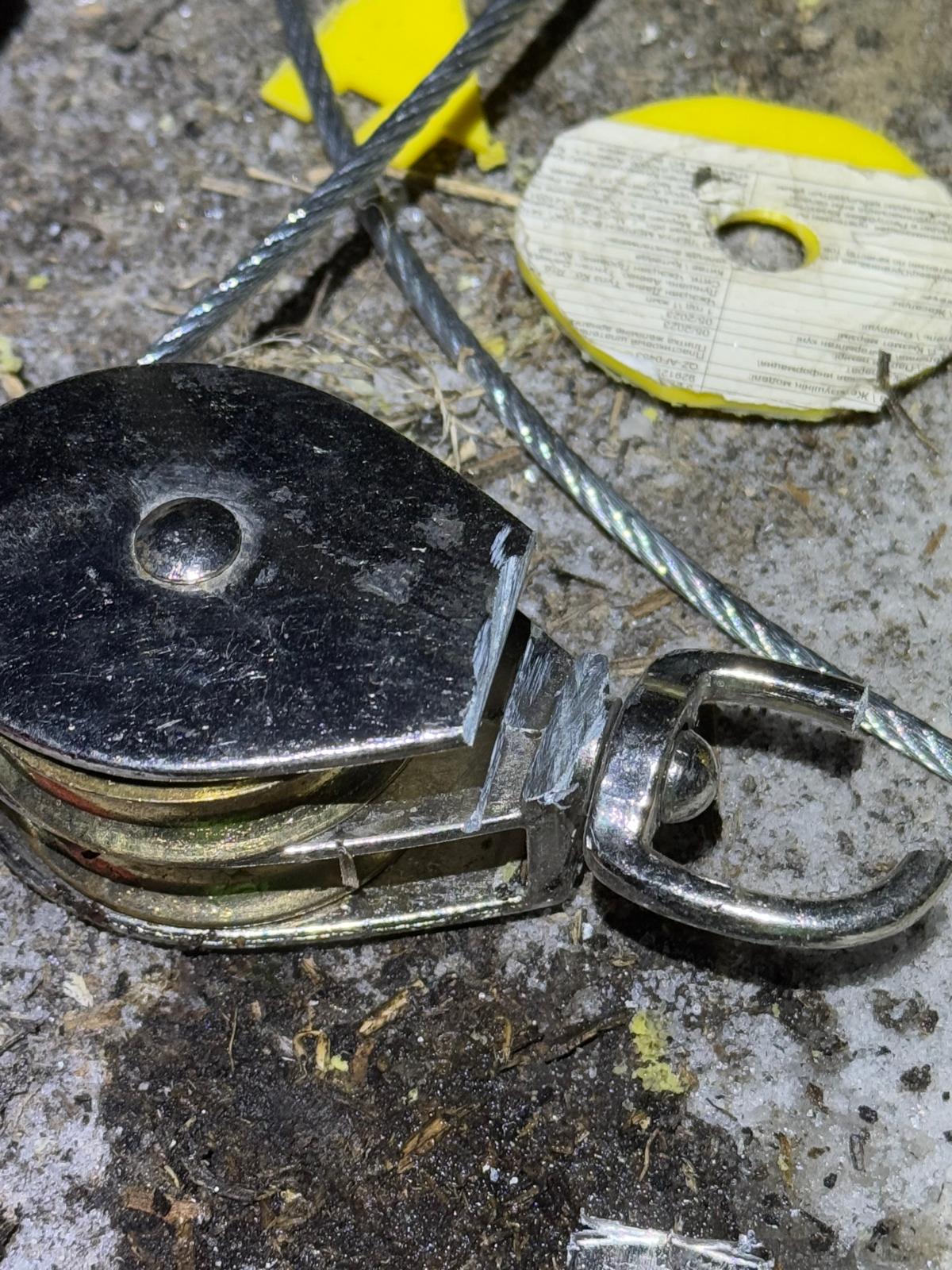
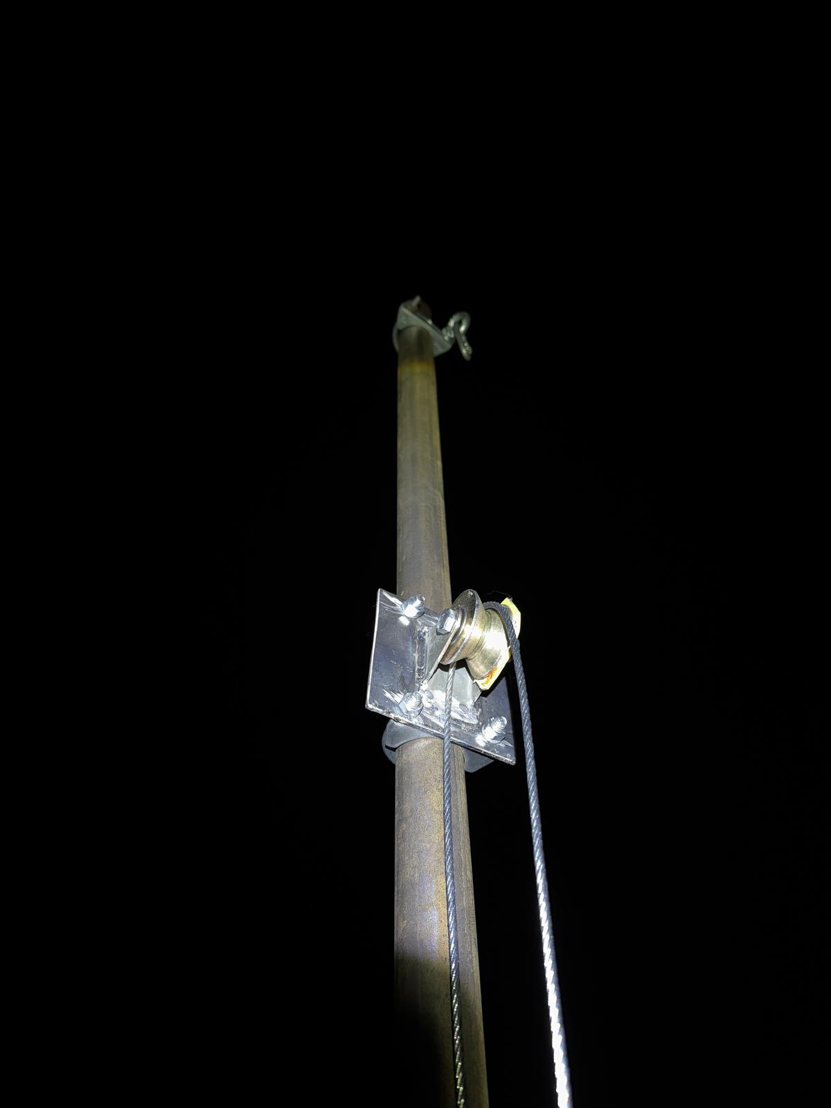
The first attempt to raise the antenna ended after 5 seconds with a boom from above… luckily, the height wasn’t big. Nevertheless, my skull has got a new scar. Not a major one, but still – an unplanned 🙂
Low-quality things kill. Be careful.
Another hour or so was spent to install a new roller.
And, finally, the antenna is about 2 meters above the ground! 🙂
- The overall mechanics and rigidness is OK
- The front part is heavier. I will have to shift the center to balance the weight
- I didn’t dare to leave it higher because a 42-mm steel tube bent too easy
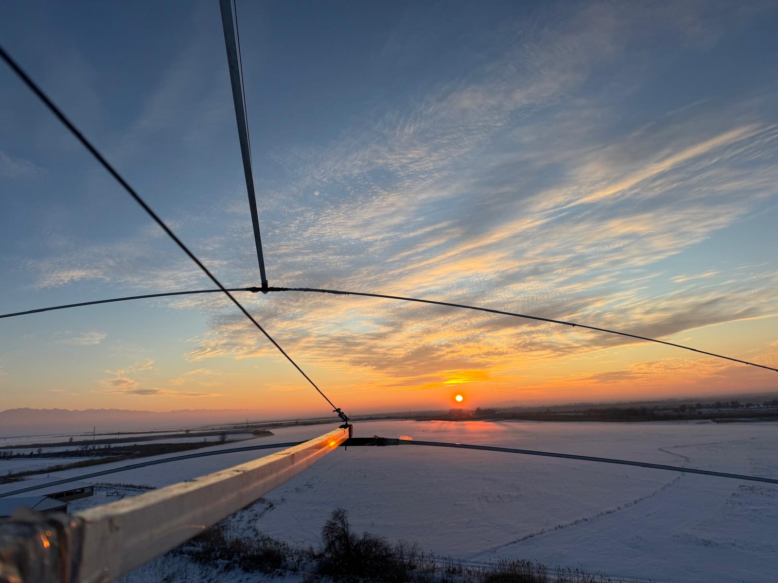
The starry beauty of the moment is difficult to describe in words.
Big open questions
- Is it really worth it? Alternative antenna variants, such as quads or vertical arrays, may be more reasonable. It took two weeks to assemble the antenna, which is a lot
- How to test it?… I quite freely modified the design using as a base the 10-meter version … But it assumes several iteration that involves easy raising and grounding the antenna …. but how? … – it is large and almost touches guys of neighboring masts… it is scratching its belly off the ground – it is not real tuning… Besides, tuning of SWR is great, but how do you test the gain before raising it to 20-40 meters of the ground? It is a too massive leap of faith. I prefer to measure and then dive into faith.
2025.Jan.25
Friday was lost because I am a family man, after all 🙂
Besides, it never hurts to do some work as well 🙂
However, Saturday came with many surprises. When I came, the wind was very strong. It is one story to calculate something and entirely another – to see how the antenna bends and rotates. It is worth experiencing that from time to time to keep an agile sense of harsh reality.
By the end of the day, I had the entire antenna assembled except for external tips – about 4 meters from each side. I really wanted to finish everything by the end of the weekend and do the first tests.
2025.Jan.23
There were a couple of days of heavy snowing, then the temperature dropped to -17C at night. Thus, I skipped those days.
However, as soon as the snow stopped, I went to the QTH to check on things. I was particularly concerned with the 20-meter antenna. I stopped receiving anything. It was either an issue similar to the 15-meter Yagi, which just disconnected somewhere, or perhaps the situation was more severe with the mast on the ground and all antennas collapsed under it. Since I haven’t installed any cameras yet, until I come, I can only guess.
The masts were OK. The antennas were in place; however, both 20-meter and 15-meter Yagis were cut off somewhere somehow… Well, I was busy with the 40-meter Yagi. Thus – one less destruction 🙂
And only the oldest babe – the 10-meter 6-element monoband has been working as well as always.
2025.Jan.21
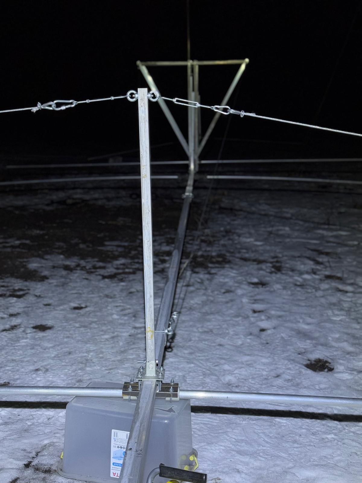
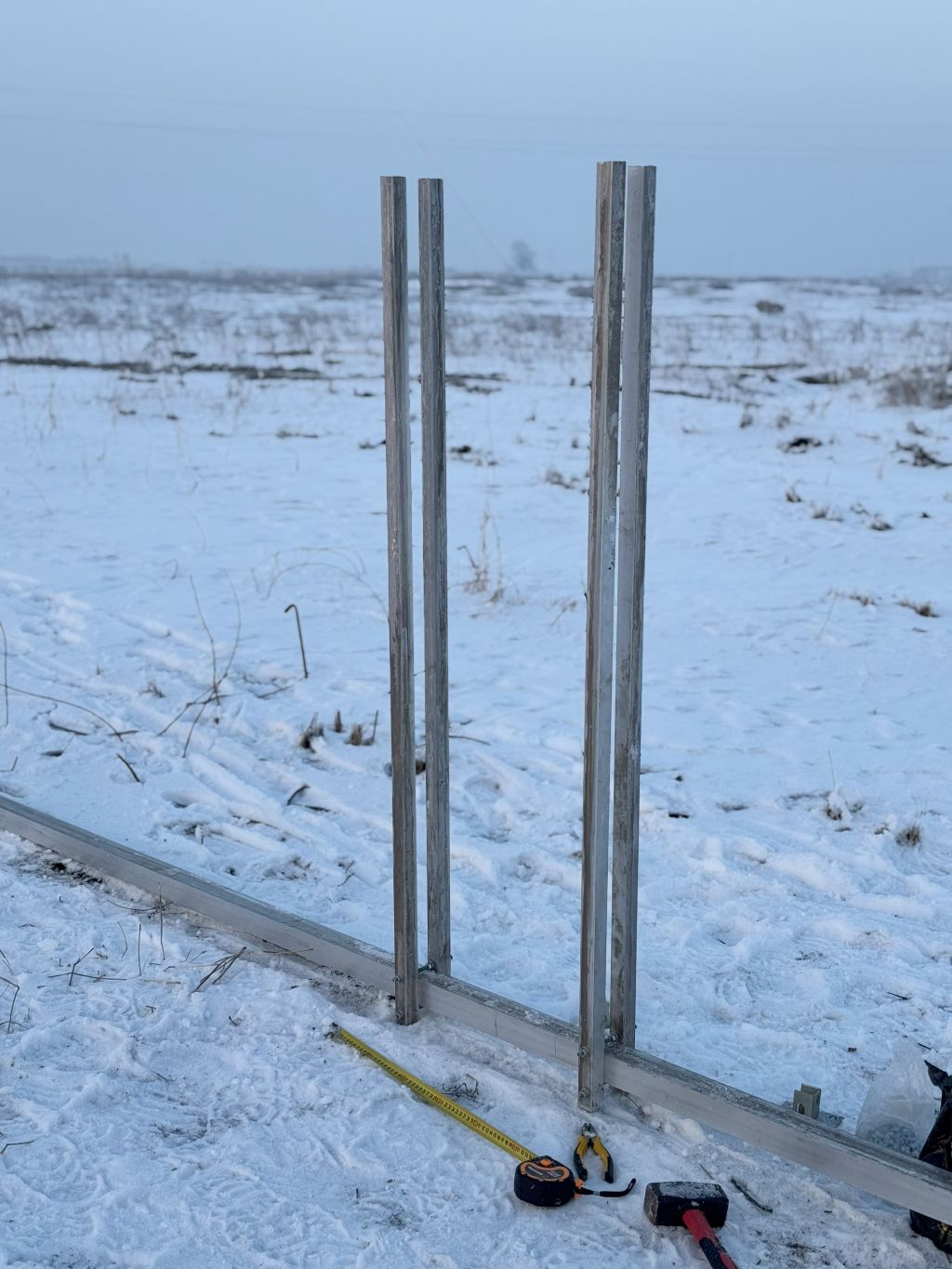
Since the reflector with a pair of supporting guys (one on the left and one on the right) worked reasonably well, the task was to replicate that for the other three elements.
The radiator was slightly different because it had a cut in the middle. Thus, I decided to use 6+6 meter tubes in the middle and longer than other elements support П-shaped steel part holding the elements.
I used the 6-meter tubes. Thus, the front element must use 3+3m tubes in the middle. Well, I have to sacrifice a potentially more robust tube for the more important element – the radiator.
The next steps:
- To make guys and support the elements
- To add remaining elements to all tubes
2025.Jan.20
I tried the new set of tubes, and it worked reasonably well:
- 2 x 2 x (3000x32x2) – sections around the boom are solid
- Maybe it is even better to have 2 x (6000x32x2)
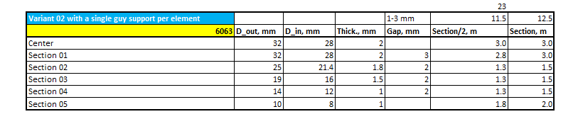
- The next sections – closer to the tips are better to be shorter and falling in diameter quicker. I am not yet reducing the diameter as quickly as my role model. They start from 48mm and end with 8mm. I start with 32mm and end with 10mm. Their profile is better, I believe. However, I couldn’t get anything larger than 32mm. Thus, reality shapes the design 🙂
- After the change, I tend to think that even a single guy per 1/2 of the element may be sufficient. Surely, it won’t be as robust as with two guys per half of the element, but adding the second guy closer to the tip doesn’t bring much rigidness to the element – rather, it bends it. Bending the external part with the second guy, bend the inner part of the element as well. Thus, adding the second guy creates more harm than help: bending, weight, wind resistance, impact on the radiation pattern, labor efforts
With the new variant of the set of tube:
- The overall shape of the 23-meter element (potential length of the reflector) reminds the seagull’s wind profile. It is certainly not an arrow. But! It looks like a reasonable compromise regarding available options, weight, wind resistance, and straightness of the element
- For example, the 20-meter 4-ele monoband Yagi doesn’t have any support for elements at all, and the tubes are smaller and thinner. The tips bent down by their weight by a meter, at least. However, the antenna survived a few pretty aggressive storms last summer (though bent mercilessly during the gusts). Performance-wise, I am very happy with the antenna: gain, front-back, and front-side
- The overall deviation from the horizontal line is about ±30cm. It goes a bit up where the guys hold the end of the inner 3+3 meter sections and going down to the end of the tip, which is not supported by the second guy any more in this design
Thus, I will take risks and continue with the design. Next steps:
- To repeat the same operations with three more elements, including the resonator
- Put the antenna down on the ground
- Install the winch on the same 6-meter tube
- Raise the antenna a few meters over the ground using the winch
- Start tuning the antenna to the proper frequency using the antenna analyzer
- Verifying that the guessed dimensions are OK with the real gain measurements, front-back and front-side measurements in the air. If the dimensions are not optimal, it is possible to shift the elements along the boom quite comfortably since they are not bolted to the boom
Other elements are shorter than the reflector. Thus, the expected bending is lower and rigidness – higher.
2025.Jan.17
It had been too smooth so far: all components were in place, there was no urgent need to rush to a market and lose time, and everything fit and worked OK … – this is not good … – it means that the hit will be strong and late – when little can be changed or adjusted and you must go to the square one more or less … 🙂
Yesterday, I started feeling that I was about to hit the rock when the element was in the air, even with the guy attached to it wobbled and bent. It means that the tubes of the element have too little diameter, they are too thin… it means that all design of the elements is just wrong … that is not good at all.
Highlights of the day:
- The vertical part supporting the elements is solid and doesn’t look like a problem
- The boom guys easily hold the weight of the reflector
- The first 6 meters of the reflector is OK but slightly bent. Bent but slightly
– The elements are too thin. Thus, even when I am using a guy, the guy doesn’t make the element straight but bends it- When the last 5 meters are bent, they bend the first 6 meters as well, and the whole reflector collapses…
It is a major problem … not yet a disaster but it is a major problem. Possible solution:
- To make more rigid elements. First, I thought to make 25×1.8 mm instead of 19×1.5 mm but now I think to extend the 32×2 mm part by 3 meters
- Thus, the new table shall look like this:
2025.Jan.16
Highlights of the day:
- The boom is stable and solid even with two guys. Smaller guys will make the whole structure even more rigid. Not too much worries about that part of the antenna. Yet 🙂
- I discovered the electric lighting thus extending the working time beyond the sunset that happens way too soon – around 16:30. But 5pm, it is completely dark
All these reminds me solo diving under ice:
- You are alone in a strange place … open field is not that much different from an open sea
- It is dark
- You do something technical that requires attention and focus
- It all is not very convenient to do alone thus basic operations take time
- You are not talking to anyone and remain in own thoughts that flow through you with their own pace
2025.Jan.15
I made notes on building the 10-meter Yagi.
But I was too busy (lazy) to record the steps on the 20-meter Yagi and then the 15-meter Yagi … and that is lost forever.
Before I forget, I will try to record thoughts, ideas, and steps while designing and building the 40-meter Yagi.
I am starting recording before I know the results. Maybe it is a major mistake. Maybe I will break my neck literally since the antenna is huge and the tower is insanely tall (I hope not :-).
I hope to enjoy the process and the result and help others with ideas.


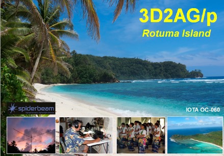
Meanwhile, Tony (3D2AG) sends from Rotuma 🙂
2025.Jan.14
2025.Jan.13


This project includes several sub-projects:
- Building the Yagi
- Building a tower
- Building a rotator and bearings
- Designing the tower erecting process and erecting the tower. Raising the antenna to the tower
I have spent 1-2 weeks heavily studying and calculating. At the end, I had 3 detailed Excel sheets with calculations, links, ideas, photos from other projects.
Some key references:
- https://antennas-amplifiers.com/40m-full-size-4el-yagi-antenna-pa7-4-18hd/ – I like the solution, the approach – many hints are taken from this design
- http://on5au.be/content/a10/ant36.html – the main source for initial dimensions before scaling
- https://www.w8ji.com/Rohn%2065G%20project.htm – hints of what is doable and what big boys do
- http://www.k3lr.com/Hardware/ – ideas from big boys
- https://www.w8ji.com/rotating_tower_w8ji.htm – on rotating tower and raising the antenna to the top
- https://youtu.be/ZzeB3FBY7Ik?si=LyOIB3kJrZtMt2cc – on rotating tower, erecting the tower, other hints
Many questions before start
How big to go
As of today (2025.Jan.15), I still don’t know what the tower will be… It certainly will be 20 meter or more… but how much more … 30 meters, 36 meters, 42 meters – I have only some vague ideas.
I have already moved to build the 4-ele OWA Yagi, so this is the first design I know of. Whether it is mechanically sound or implementable, I’m not sure yet.
Tower size
Would it be 40cm on each side?… 50cm? Triangle? Square? 6-meter sections? Or 6-meter sections and then 3-meter sections?
How to erect the tower
- I erected the tiny 10-meter alone using the gin pole method
- With the help of a few friends, we erected the 18-meter tower for the 20-meter Yagi using the same method. Even more, after special add-ons, I can lower and raise the tower with antennas on it all by myself
- But a 30- or 40-meter tower is too tall for that … Using a crane? Or should I raise the first 18 meters with the gin pole method and then gradually add a 3-meter section one by one?
- Or use a crane like the Irish did?
To build the concrete base or not
I have never done anything with concrete. At all. And I rent a plot on a farm for the QTH … it may be not a good idea to destroy the plot … but erecting a 40-meter tower without a concrete base is maybe the worse idea …
To build one or many antennas on the tower. A rotatable tower or a rotator
The tower is a huge investment of money, time, effort, and space. I want to try a stack or two on it.
I built a regular tower. A rotating tower sounds like a nice challenge. Whether it is doable and reasonable – I don’t know yet (2025.Jan.15). But after thorough checking of inner desires – that is the driving whim 🙂
If the tower is rotating, then the rotator and orbital bearings are things of their own
These things are complex, heavy, and expensive. The best hints and ideas:
- https://youtu.be/ZzeB3FBY7Ik?si=LyOIB3kJrZtMt2cc – again the friends from Ireland
- https://ant-depot.ru/catalog/povorotnye-ustroystva/ra4lw-ring-rotator/?oid=58991 – rotator
- https://www.oh8lq.com/index.php/making-towers-and-antennas?view=article&id=18:guy-rings&catid=2:uncategorised – found on Feb.17., 2025 – much later than I started designing
How to lift the antenna
Many technical decisions are closely interlinked. Lifting the antenna to the tower is one of the key steps.
What materials to use
After reading, studying, and calculating, АМг5 or АМг6 or АМг5M or АМг6M were selected…
After getting the first quotations and budgeting the idea, I scaled back to my noname supply from a local noname market of a noname alloy 🙂
I have been hinted that the tubes I finally purchased can be the 6063 alloy. But that is unconfirmed. Well, I again build from what I have – not from what I would like to build 🙂
It is valid not only for the alloy but also for the dimensions of tubes for elements and for the boom.
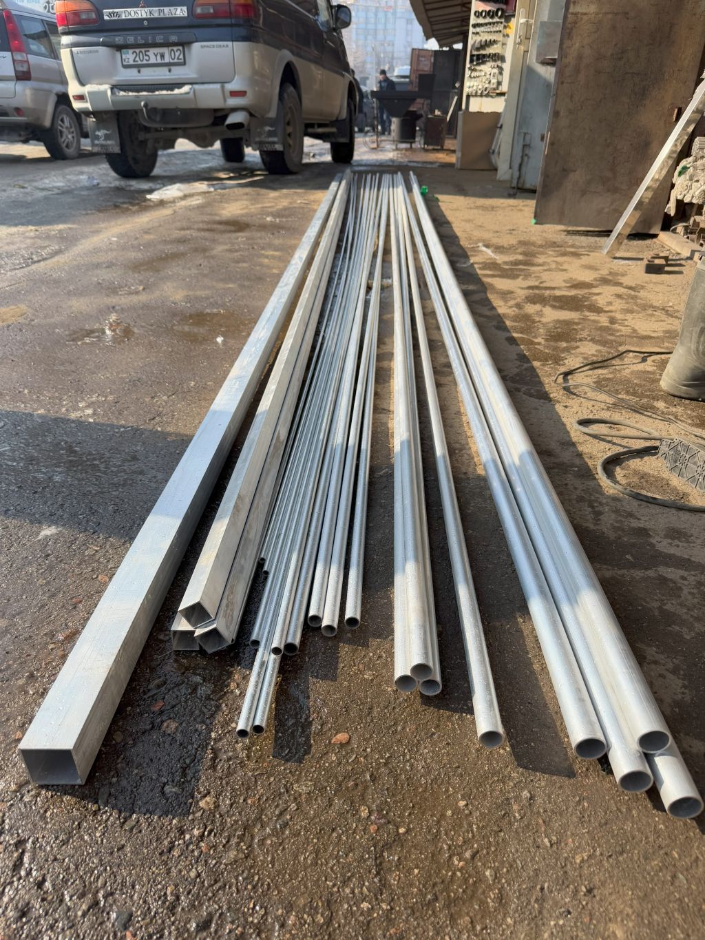
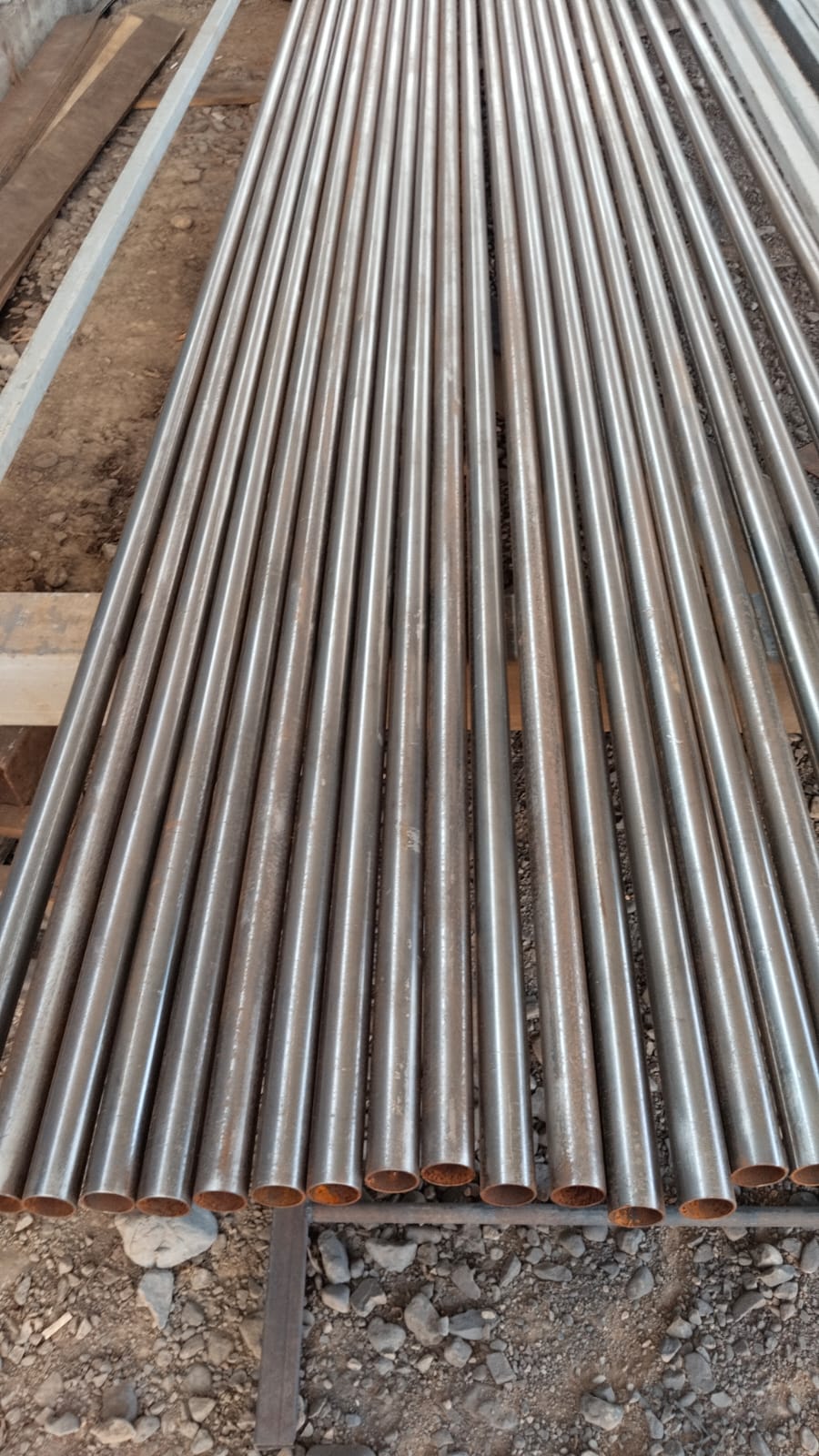
Eventually, I purchased the following volume for elements:
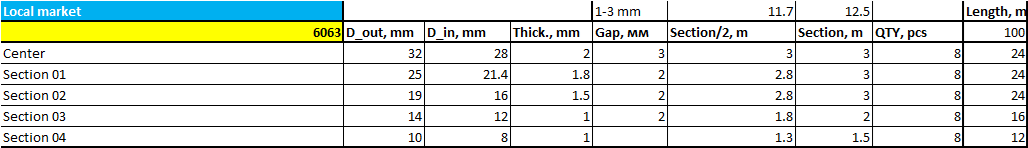
For the boom and the support:
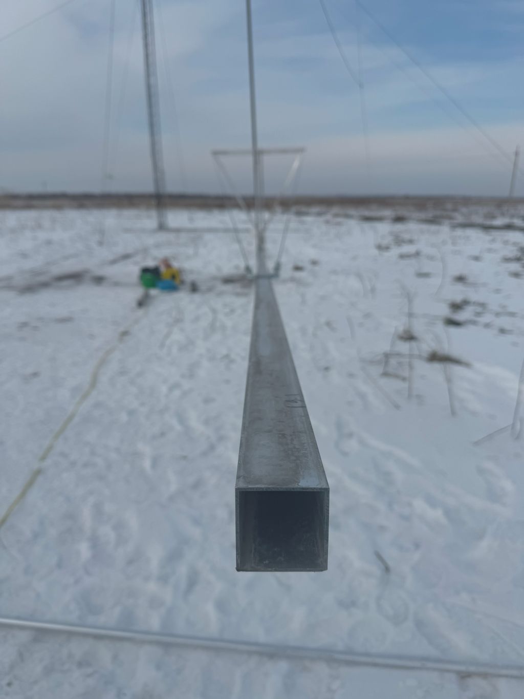
- 6000x50x50x2 – 3 pcs. I thought to buy an additional piece as a central element for more strength. But this tube was the most expensive, and I thought I would buy it later if needed. Though delivery to the QTH, which is 60 km away, can be expensive, purchasing something I may not need was expensive too …
- 6000x30x30x2 – 3 pcs for boom support and for elements support